


How to set filter specification for Decimation process
Hi, i'm new to DSP so i'd like to understand something about decimation. This is what i have : a sinusoidal signal,about 200MHz sampled with a 500 MSPS ADC then demodulated and filtered(lock-in).The signal is completely buried in the noise. The problem is the filtering process because the sampling rate of the system is 500 MHZ(clock). I need to select a bandwidth of about 10 KHz so the only way to do this is implementing a multirate filter. Problably i misundersand something about decimation but i'm not sure about the design of the antialiasing filter before the decimation. From the frequency domain the spectrum spread every decimation process but in this case,that the aliasing is unavoidable due to noise, i don't understand the optimal number of cascaded filter that i have to put in the design. I'm using simulink and these are the two options that i can choose:
1) fir decimate block
2) manualy put a filter and a decimator
In both case i use Fsample= 500MHz
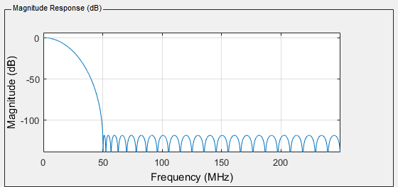
case 1) automaticaly generate the magnitude response by knowing the sampling frequency and the decimation factor, this is what a get:
_45498.png)
case 2) do i need that flatness? As i sayd early, the aliasing is unavoidable in my case and the information is demodulated near 0Hz. So that's the question: can i design a filter like this? less multiplier are required and a -3db point of around 10 MHz allow to downsample to 50 instead of 5
I'd like to thank with everyone that will help.

The rule of decimation (assuming Fs_in, Fs_out) is that:
1) If there is no power beyond Fs_out/2 then you can decimate directly. This doesn't apply to adc acquired signal.
2) If there is power at Fs_out/2 then cutoff there (or earlier if it helps next stage).
your thoughts about noise ...etc aren't clear. There is noise, yes but you don't want to concentrate all the noise into smaller and smaller band so you must cut it off before decimation(else it aliases into new shorter band).
With multistage decimators you may allow some aliasing if you know you are going to chop it off later in next stages.
I suggest you use cascade of FIR decimators or use CIC
I'll try to use CIC filters. Thanks again

Quoting things out of order:
"I need to select a bandwidth of about 10 KHz so the only way to do this is implementing a multirate filter."
No. If you need a bandwidth of about 10kHz, you need a filter, to be sure, but there is no fundamental need for it to be a multirate filter.
It may be more convenient to use a multirate filter, because if you're truly only interested in a 10kHz bandwidth then there's absolutely no need to sample faster than 100kHz or so, and you can get away with less.
"The problem is the filtering process because the sampling rate of the system is 500 MHZ(clock)."
And this is a problem because? I assume you mean because you have that sampling rate and not enough room in your FPGA to run the whole processing chain at 500Msps -- but again, there's no fundamental reason you can't do it at 500MHz throughout.
"A sinusoidal signal,about 200MHz sampled with a 500 MSPS ADC then demodulated and filtered(lock-in).The signal is completely buried in the noise."
I sincerely hope that you're contemplating doing the demodulation before you do any decimation. I also hope that you're considering the fact that your 200MHz signal has an alias at 300MHz after sampling. You should be fine with the problem as you've laid it out, but if you need to lock onto a signal at much higher than 200MHz you may run into problems.
Are you steering the demodulator frequency with the output of your 10kHz-wide filter? Or are you just filtering to 10kHz wide and amplifying? If the former, then your filter is inside of a feedback loop, and things get complicated -- I'm not going to go into how, but do tell us if that's the case.
Sorry i mean that 10 Khz is obtainable only if you use a multirate stage cause using a single stage results in extreme lenght of the filter. 500 Mhz is a problem for what i sayd just now about filter, is the frequency that i need to generate the sinusoidal signals with a DDS and i can perfectly run at that frequency,the problem is related to filtering. So i'm completely agree with you about these suggestions. The max frequency i need is 200 MHZ so the alis component at 300 MHZ is not a problem and yes, the demodulation is done before the decimation. I'm in the latter case, i just need to filter as much noise as i can so for now i just suppose to select 10 KHZ of BW. Thanks for your suggestions, best regards.
I don’t totally follow what your requirements are, but I’m happy to share what I know about it. It sounds like you want to apply a filter to your signal, but your sample rate is prohibitively large. If that is the case, I believe the best tool for the job is a polyphase filter, such that the resampling and filtering take place in a single operation, providing a more efficient implementation. Alternatively, you could use an aggressive CIC filter and decimate after it.
In terms of specifying the filter, you need to define the decimation factor, I.e your output sample rate. This should be equal to 2 times your desired bandwidth plus some margin. The transition band is the difference between your output nyquist frequency and your desired bandwidth. The smaller the transition band and the higher the attenuation, the longer your filter needs to be. In other words, by building in more margin, the less computationally expensive your filter becomes.
With that in mind, I don’t understand why your transition band in the first example doesn’t start at 10Mhz, which I assume is the desired output bandwidth. Next, the size of the transition band sets your filter complexity. Lastly, your decimation factor sets how much aliasing occurs. If nyquist occurs at or above that first null, aliasing should be minimal. If you set it lower, aliasing will occur and it becomes a judgment call as to how much you can stomach. Hope that helps
Thank you very much
Firstly SNR depends on inband noise and out of band noise. With filtering you can reduce out of band noise or leave to alias and so reduce SNR relative to ADC output. You will never be able to remove inband noise.
The cutoff frequency depends on your requirements i.e. what bandwidth you want to end up with. In the decimation stages you follow that rule I explained earlier. Cut off at Fs_out/2 of that stage or less or more provided next stages are aware what to do.
ok that's clear,thanks again
Yeah. When you spec a decimation filter, it’s not so much the ‘cutoff’ that we’re talking about. Instead, we talk about the pass, transition and stop bands. You want the stop band to begin at the output nyquist frequency to minimize aliasing. If your pass band ends at the nyquist, all of the transition band will alias. To your point, the designer can decide how much aliasing they can tolerate and choose the decimation factor and anti aliasing filter accordingly
perfect,thanks ;)


