


Is there a way to mathematically prove whether the convolution of a digital signal will lead to digital clipping?
Hello,
I had a question regarding the convolution of digital signals.
Assuming the following digital signal:
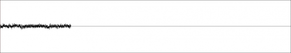
...is convolved by the following digital IR signal:
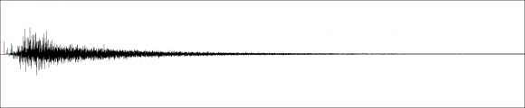
...is there a way to tell through some calculation whether digital clipping will occur:
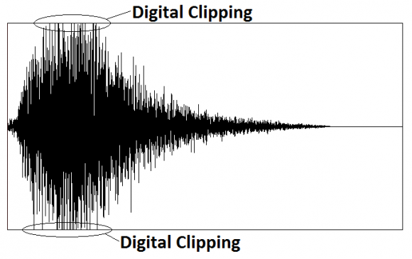
...or not:
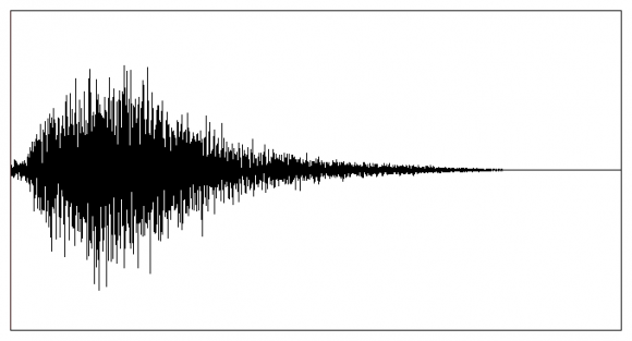
...before we perform convolution?
If I had to guess, I'd need to perform some sort of operation on the FT (Fourier Transform) for both digital signals, but I'm not sure what that would be.
Furthermore, if it is possible to perform such a calculation.
Can we also tell what sample (either in the digital signal being convolved or the digital IR signal) leads to the digital clipping (in order to remove that sample and any other samples that follow) to avoid any digital clipping from occurring when we actually perform convolution?
Thank you,
Nelson

This is not a mathematical proof, but maybe it helps to lead you to the right track...
- Convolution is basically nothing but multiplications and sums.
- Clipping is not the result of neither multiplication nor summation.
- For both signals there is a representation in any number system and range.
- Mathematically, integer values build a coset (residue class).
Behavior at the borders of the coset must be defined for multiplication and for addition, first mathematically, and then it must be implemented in your tools by software/hardware. - This is the same (though different) for fixed point or floating point values.
As an easy example imagine that you have a typical signed 4bit binary representation (two's complement). It ranges from -8..+7.
Now assume, from beginning with 0 we continue to add 1 to a number. We get:
0,1,2,3,4,5,6,7,-8,-7,-6,-5,-4,-3,-2,-1,0,1,2,3,4,5,6,7,-8,-7,...
This might look like clipping, but it's not. It's just wrapping around.
Mathematically spoken: the summation behavior of this coset is defined in this way.
You call such a coset, if summation cannot leave the class on the borders, a residue class ring (which has some very pretty attributes ;-)
But in your case it obviously reveals this nasty behavior which looks like clipping.
If that's possible, scale the signals differently. If you make it smaller, there should be less clipping, if you increase the level, clipping should occur on more points. This would be an indication, that your value range cannot handle this convolution.

For FIR case yes there is math for clipping case.
convolution max output = multiply magnitude of each coeff (without sign) by peak of your input value and accumulate.
for input of n bits signed
max output = sum(abs(coeffs))*2^(n-1)
You can then scale coeffs to stop clipping. This takes worst case input (peak dc value) and with sign that changes all products to same sign.

I'll just concur with kaz that what he described is the way to do it: multiply the sum of the absolute values of the convolution coefficients with the max input value. If that value is less than the max that can be represented in the number format of the convolution output, then there cannot be clipping. Otherwise, it is possible.
How often clipping happens will depend on the input signal. An input with signs that match the signs of the convolution coefficients can produce a large value, and if the input magnitudes are large in that condition then clipping becomes more likely.
Hello Kaz,
A big thank you for the response.
I can't thank you enough.
Nelson
Hello Kaz,
This is an extremely stupid / silly question, but are you sure we perform the sum of all values:
sum(abs(coeffs))*2^(n-1)
...when calculating if digital clipping occurs when convolving a signal A by an IR B?
I only ask as a dB is defined as the ratio of two values, such that a doubling of values results in an increase of 6 dB (rather than a linear increase of 2x).
Thank you,
Nelson
yes I am sure. The usual belief is that if you apply a signal at full dc then that determines max possible values of sum of products i.e. for
x(n-2)*h1 + x(n-1)*h2...etc and using dc at 32767, the max sum would become:
32767 *h1 + 32767*h2...
= 32767*(h1+h2...) = dc * sum of coeffs.
That is partly true because if dc changes sign you could get larger value.
The dB you are talking about has nothing to do here. You will target your power gain as required. We are talking about internal sum. The actual output will be less bits.
Bear in mind that such extreme case of clipping need not be accounted for at the expense of your most likely signal dynamic range..
Hello bholzmayer,
Thank you for the detailed response.
Nelson

Nelson-
How much "some calculation" are you willing to tolerate and why is there an a-priori need to know ? The excellent answers from Bholzmayer, Kaz, and Slartibart seem to be aimed at low calculation cost, but they are worst-case methods and could predict clipping when in fact it wouldn't happen.
Probably a mathematically sound way to get a better estimate is to FFT the smaller signal (the "filter") and look in the freq domain to see if magnitude is more than 1, if so there may be some gain on your convolution output. If not you know it won't happen, for example FIR filters are typically designed to have a gain of 1. Of course that method takes a significant percentage of calculation vs. the actual convolution itself, and it still would not tell you the exact sample(s) where clipping happens.
-Jeff
True, practically I will never restrict coeffs for those extreme case. I will target unity power across a function or move gain up/down as required in various scenarios. For high values I can either clip or let it overflow and in both cases we get some nonlinear effect. A flag/counter will help any further action.
Hello Jeff,
1. Just to recap, can I assume that whether we use a more exact (ex. your approach) or least exact (ex. Kaz's approach) estimation, that ultimately, there is no way to pinpoint which sample in an input signal (being convolved), will trigger digital clipping when convolved by some IR?
2. If the answer to question 1 is yes. Would you happen to have an idea of the difference between the false positive rate of Kaz's approach compared to yours? In other, would Kaz's approach incorrectly identify digital clipping in a digital signal being convolved by some IR, 2x or 10x more often than your approach?
2. How much of a difference are we talking about between your approach and Kaz's (computationally speaking)? Are we talking about something like 10x or 100x increase in calculation time? Or something more on the lines of some exponential increase in computation time? I only ask as Kaz's estimation is sufficient for my purposes if the increase in computation time between your approach and Kaz's is extreme.
Thank you,
Nelson

Of course this is possible and often necessary. Like already mentioned the coeffs have to be investigated but also the incoming data. If for instance there is a non symmetric data stream like with video, there ar no negative coefficients wich have to be taken into account. With audio we can estimate symmetric signals from -1 ... +1 and so the accumulation of the absolute values of the coefficients is the solution.
Regarding optimization, i often scale the coeffs that way, that the sum up to something like 65535 or another value of "n power of two - 1" to be able to devide easier, especially in integer systems like FPGAs.
This is most appropriate for signal analysis and pattern recognition. In very special cases the spectrum of the incoming signal can be taken into account too.
In order to maintain the true power information, scaling with have to handled over all possible filter configurations and convolution coefficients especially when changing parameters during real time processing like sound synthesis with FIR and such.


