


Hello
I am a bit confused with the phase response of filters... I think I do not yet understand completly the topic... I'm playing with a very basic filter... a recursive peaking comb... and when I combine the filter with a delay (two systems in series with the delay either before or after) I get a very weird phase response...
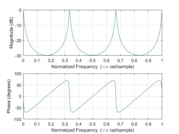
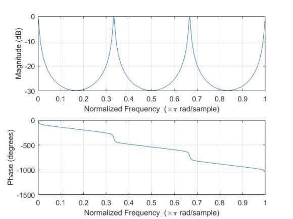
The original filter is $$ H[z] = \frac{(1-a)}{(1-az^{-N})} $$ while the filter delayed (again combination of the original pluse a delay) is $$ H[z] = \frac{(1-a)z^{-N}}{(1-az^{-N})} $$
For the both I get the same magnitude response as expected... but when plotting with matlab the first increases and decreases with phase jumps in the peaks while the second one is giving me kind of decreasing phase with pahse jumps in the peaks... you can see in the following plots, the original;
The delayed;
Could somebody add some light to the physical meaning of this difference and why it happens only delaying the response of the filter?
Thank you

To see what's happening, separate the filter into 2 parts.
Plot the phase of z^-N. You are just adding that phase to the original.


can you show how you enter matlab to get mag/phase please
Hi Kaz,
mag: plot(20*log10(abs(H)));
phase: plot(phase(H));
plot(angle(H)); if you wanted wrapped
I can see your work is correct and the replies given here are useful.
To explain it there are two perspectives:
1) complicated one say you got two systems:
assume a = .5;
freqz(1-a,[1 0 0 0 0 0 -a])
freqz([0 0 0 0 0 1-a],[1 0 0 0 0 0 -a])
2) simple case of delay.
for a given input your output is exactly same stream apart from constant delay of 5 samples delay.
grpdelay(1-a,[1 0 0 0 0 0 -a])
grpdelay([0 0 0 0 0 1-a],[1 0 0 0 0 0 -a])
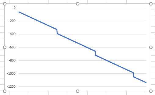
total_delay[n] = org_delay[n] + const_delay[n]
org_delay[.] = a 3 cycle sawtooth with pp of +/-60 degree.
const_delay[.] = half cycle sawtooth starting with 0 and ending at -1080(3*360).
if you do the above math the plot is going to be.
Hi All, thanks for the quick reply... and going a bit depper in the question... and looking for a physical meaning of that phase...
a) I understand that for the combined filter(delay and IIR with normalized gain) the "phase shift" the it introduces to a single tone depends in the frequency of the tone, (according to the plot for 0.9 normalized tone it would be a bit less than 1000 deg), and that this value increases with ferquency due to the delay which has a stepest slope than the IIR. Is this right?
b) Looking only the IIR it seems that the phase shift introduced by the filter is sometimes positive, and some times negative... I know that linear phase shif filters are FIRs and not IIRs... but is it normal the IIR has a positive slope instead of a negative one, and some times adds a positve shift and others a negative?
c) Looking in detail the resonances... there we find "phase jumps"... In the plots I can see these are arond 120deg (+/-60deg)... should this be 180 instead of 120?
d) A bit more of fun with phase delay and group delay, when I computed them and plot it in the following picture (top only filter, middle only delay, bottom combination)
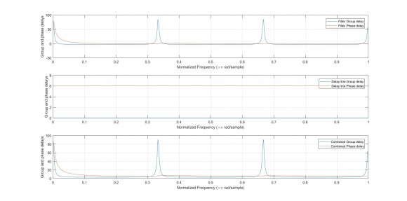
I can understand that phase delay for the pure delay is the time it takes any tone to "cross" the filter, which is the same for any frequency... but then in the other plots... this is variable... does this make sense looking it from a physics point of view? should any signal take the same time independent of the frequency to "cross" the filter? why we don't see this behaviour then in the IIR (I understand again the combined one is the combination of IIR and delay)... and I'm lost with the group delay...
Thanks a lot
Hi Rockymarx,
phase delay is not how much time it takes to "cross the filter". It is how many periods of the sinewave it takes to do so, that's why it's different for each frequency. You are confusing it with a group delay - which is exactly the time it takes for each frequency to go through the system and it is constant for a constant delay line.
The group delay is a negated derivative of the phase, so linearly decaying phase response means constant positive time delay.
The Wikipedia page has it all covered nicely:
https://en.wikipedia.org/wiki/Group_delay_and_phase_delay
Best regards,
AXP
Hi AXP,
I think Rockymarx meant constant delay when he mentioned phase delay.
obviously these terms constant delay,phase delay,group delay are confusing
fixed delay (system) be it piece of wire or registers as you noticed just causes delay and this changes phase linearly. i.e. if you inject a sine tone through 5 registers then output will only appear after 5 delay stages being zero before then the tone will be copy of input. If you change frequency of tone you get same tone back. Common sense otherwise we would have lots of troubles in real world...remember each sample is delayed by same constant no matter what frequency is used.
symmetric and antisymmetric FIR systems also lead to linear phase change in the same way as piece of wire with minor difference at initial segment which is within group delay samples. These samples build up gradually and is not very nice...as if you have so many registers but each outputs fraction instead of zero. If you set filter input to zeros at end but keep it running then a tail will also appear mirroring the startup.
IIR systems are based on feedback terms and the delay caused varies with tone frequency. The group delay tells you that in samples (including fraction of samples). The initial or tail samples will vary with frequency of tone.
non symmetric FIR and IIR behave like that "by nature" and I really don't know how to imagine it physically. Just like I don't know why a filter cuts off when it should.
By the way when one tries fft on filtered stream the start/tail of filtering can have significant effect compared to regular stream and should be cleaned off at fft input. Yet obviously this does not apply to register delay/wire which is clean by nature.


