


Hi all,
I need some help to design a CIC Filter. The #CIC Filter I am trying to design has following properties:
Decimation factor R= 10
Differential Delay M= 2
Stages = 5
Input Sample width = 14
Output Sample width = 24
When I am designing this filter in matlab I am facing some problem.
For test, I apply sinusoidal wave at input of 2MHz frequency at a sampling rate of 120MHz. In the output signal spectrum I observe a strong DC component for 24 bit wide output.
I tried output width 36 and there was no DC component. So most probably truncation is causing the spectrum to change.
Is there any way of truncating the output bits so I don't get distorted spectrum at the output?

Hi.
The gain of a 5th-order CIC decimation filter is D^5, and individual integrators
within the filter can experience overflow. (An integrator’s gain is infinite
at DC!) As such, the use of two’s complement (non-saturating) arithmetic resolves this overflow situation just so long as the integrator word width accommodates the maximum value expected at the CIC filter output. Happily, using the two’s complement binary number format, with its modular wraparound property, the follow-on comb filter will properly compute the correct difference between two successive integrator output samples.
dkgupta, apply a low-amplitude input sine wave to your CIC filter and monitor the output of the adders. See if the adder outputs look correct, or do the outputs have unexplained disconituities caused by arithmetic overflow.
For a Q-stage CIC decimation-by-D filter (diff delay = 1) overflow errors are avoided if the number of integrator and comb register bit widths is at least
register bit widths = number of bits in x(n) + {Qlog2(D)}
where x(n) is the input to the CIC filter, and {k} means that if k is not an integer, round it up to the next larger integer. For example, if a Q = 3-stage CIC decimation filter accepts one-bit binary input words from a sigma-delta A/D converter and the decimation factor is D = 64, binary overflow errors are avoided if the three integrator and three comb registers’ bit widths are no less than
register bit widths = 1 + {3 log2(D)} = 1 + 3 6 = 19 bits.

Wouldn't a 5-stage, decimation of 10 CIC filter also have a bandwidth of roughly 1/10000 of the sampling rate? So at an input sampling rate of 120MHz, wouldn't a 2MHz signal both get attenuated down to nearly nothing and aliased to some practically random frequency?
Thank you Sir for your reply and i understood where is the problem in my design.
In my case the gain is (10*2)^5, which is increasing the output width by 22 bits. So there are 14+22= 36 bits required at the output. But if i want to use only 24 bits at the output. Then i need to truncate 12 bits from the output.
I think the problem i observed was because i was using 24 bits at all stages of the CIC filter, which must not be the case. As you have written that integrator word width must accommodate the maximum value expected at the CIC filter output.
According to E. B. Hogenauer paper on CIC filter, instead of applying truncation at the output directly, we can apply truncation at different stages of CIC filter. So Can you please explain to me, how can i truncate bits at different stages of CIC filter?
And is there any explanation to why there was a DC shift when i used only 24 bits at all stages of CIC filter instead of required 36 bits?
Thank you..
Hi
You wrote:
“In my case the gain is (10*2)^5…”
That surprised me. I haven’t experimented with CIC filters when the differential delay = 2.Does the ‘2’ in your ‘(10*2)^5’ come from your differential delay value?
As for your question regarding “truncate bits at different stages of CIC filter”, that’s a tricky subject. Years ago I posted MATLAB code here on dsprelated.com that would tell you how many bits to use for the accumulators in each stage of a multistage CIC filter. But now I can’t find the ‘software code section’ here on dsprelated.com.
I’m away from my office right now, but if you send me a private e-mail tomorrow (Aug. 29, 2016) I’ll send you my MATLAB code for determining how many bits to use for the accumulators in each stage of a multistage CIC filter. Who knows, that code may be of some help. My e-mail address is: R dot Lyons at ieee dot org.
As for your last question regarding what you call “a DC shift”, off the top of my head I can’t explain what you are experiencing in your Simulink modeling. I don’t use Simulink.
Hello sir,
Yes sir, in all the texts i have come across related to CIC filter, they have mentioned that gain for CIC filter is (RM)^N, where R is decimation rate, M is differential delay and N is number of stages. And i tried to verify it with matlab also.
Exp: I used a CIC block with R= 2, M= 2, N= 2, so it must provide a gain of (2*2)^2= 8. Following figure shows the input and output signals.
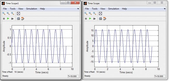
On the left is the input, which is a sine wave of amplitude one and on the right is the output with an amplitude of 16 as expected.
Sir, i think i have just found the MATLAB code you are referring to.
https://www.dsprelated.com/showcode/269.php
I will try this code if this is the code.
Thank you very much sir for your help.
Hello dkgupta,
You wrote "(2*2)^2= 8" and you meant to write, "(2*2)^2= 16".
In an earlier post you wrote "(10*2)^5" and I said that surprised me. Thinking about it later it finally occurred to me that a diff delay = 2 is equivalent to doubling the length of the moving averager which is what a CIC filter is. So your (RM)^N makes perfect sense to me now.
I'm happy you found the MATLAB code web site. (I have replied to the e-mail you sent to me.)
Deepak, I was wondering. Does the input signal to your CIC filter have an average value of zero? I hope it does because your CIC filter will amplify your input signal's DC component by (10*2)^5.

@Rick your code is available here: https://www.dsprelated.com/showcode/269.php
Hi Chris. Thanks!
[-Rick-]
As a DSP beginner implementing a CIC filter recently, I wanted to add something to this. I know this is a very old post, but I'll add to it anyway.
I found Rick's various online posts about CIC filters very helpful, and the equation for word width is correct. However, in circuit design we often think of 1-bit sigma-delta ADCs / modulators as outputting +1 or -1 or "up" / "down", not 0 or 1. In fact, +1 is not representable in 1-bit two's complement integers; they can only represent -1 and 0. So, if you want "zero average" to be represented as the value 0, rather than -0.5, you may want to use Bin = 2 despite having a "1 bit input". This requires an extra bit throughout the CIC filter, but this has what I would call an advantage that there is no difference between initializing all the logic to zero and processing a zero-valued input signal.

Can you please explain how you are implementing your CIC filter? Are you aware of the problem with overflow in a CIC filter (http://www.informit.com/articles/article.aspx?p=36...)
Hi, Thanks for your reply and interest in my query.
I am implementing this filter in simulink using inbuild block. Yes, i am aware of overflow in a CIC filter. And i have book by Fredric J. Harris on Multirate filters with me. i think the problem was that i was using only 24 bits at each stage of the CIC filter instead of 36 bits as required for the configuration.
But is there any way to use 24 bits at each stage without distorting the output much?

Hello,
If you look at the original paper you will find the equations for bit growth at each stage. So yes, the required adders can be large. You cannot truncate to an arbitrary bit width in the middle: the latter stages depend on the overflow happening in a certain way. Also, yes, the DC gain can be less than one, easily compensated by other stages in the chain. I typically model these in simulink; we have done a few so it is a cut and paste design. Also, I usually have a FIR filter to compensate for the droop in the pass band; depends on your application.
Hi
Thanks for posting that web link address. That link is useful because fred harris’s book is ‘Out of Print’.


