


Designing an IIR comb (peak) filter
Hi there,
I'm trying to design an IIR comb filter to keep only 10 Hz harmonics in a noisy signal which is periodic at 10 Hz for noise rejection. The comb filter should then have peaks at 10 Hz, 20 Hz, 30 Hz ... (probably up to 200 Hz), and low amplitude response for other frequencies.
This is the code I've been working on in MATLAB: IIR_comb.m
When I run the code, the figures I get look like complete mess.
I'm not too concerned about performance trade-offs at the moment - just trying to get a sensible response for now.
Cheers

bobby_k,
Your sample rate is 15 kHz. So you can decimate by 4 to 3750 kHz. Then this code gives the response you are looking for, I think.
regards,
Neil
fs= 3750;
b= [1 zeros(1,374) 1]/2;
[h,f]= freqz(b,1,8192,fs);
plot(f,abs(h)),grid
axis([0 200 0 1]);
xlabel('Hz')
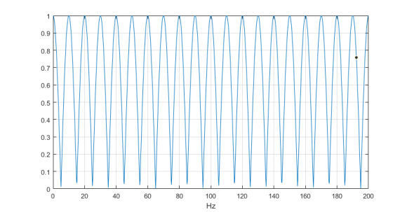

Nice thing is this can be implemented with 1 adder and a memory.
Hi Neil,
Thanks for the help.
Could you please explain a few things with your design process?
1) Why did you downsample by a factor of 4?
2) It would seem that your filter is an FIR filter (since denominator in freqz is 1), how did you select these coefficients?
3) What's the significance of 8192?
Cheers
bobby_k:
1. Since you said your band of interest was 0 -200 Hz, it is ok to decimate by 4 to give fs= 3750 Hz. You don't have to decimate, but if you don't, the comb filter is 1501 taps instead of 376 taps.
To decimate, you would need to use a decimation filter, not just downsample. For example, a very simple decimation-by-4 filter would have coefficients
[1 1 1 1]/4. Then you downsample by 4 after filtering. As I noted, decimation allows shortening the length of the comb filter by a factor of 4.
2. Yes, it is FIR. See this article for the theory:
https://www.dsprelated.com/freebooks/pasp/Comb_Filters.html
3. 8192 is the number of frequency bins computed by the matlab function freqz - freqz just computes half the points of a 16384-point fft, and computes a frequency vector f.
regards,
Neil

Without going into details of your code... your poleAngle and poleCoeff is updated inside loop for each value of i and takes in last value. Are you aware of that
Hi kaz,
Yes, that's correct. I'm placing a pair of conjugate poles per iteration of the for loop (at increments of 10 Hz) and multiplying the transfer functions each time to yield the overall transfer function.
cheers

Hi bobby_k
I tried to run your code but it contains calls to functions 'tf()' and 'tfdata()" that I do not have.

it turns out that *every* digital filter is a comb filter (of sorts). if the digital filter is a LPF, you will see comb teeth at every integer multiple of the sample rate $n \dcot f_\text{s} = \frac{n}{T_\text{s}}$. if the digital filter is a HPF, you will see teeth halfway between every integer multiple of the sample rate.
now change your unit sample delay $z^-1 = e^{-s T_\text{s}}$ to a longer delay that i will express only in the continuous $s$-domain: $e^{-sT}$ where $\frac{n}{T}$ are the frequency you want to tune your teeth of the comb to.
so you need to make a precision delay to tune it to exactly the fundamental frequency you want, and then you can design the teeth of the comb filter just like you design any old LPF.
and i still haven't figured out how to do $\LaTeX$ here at dsprelated.

$$ H(z) = \left(1 - d \right)\frac{z^N}{z^N - d} $$
Choose $$ N = f_s / 10\mathrm{Hz} $$ and make d as small as you want your peaks to be pronounced.


