


Power-Normalized Waveguide Filters
Above, we adopted the convention that the time variation of the wave
impedance did not alter the traveling force waves ![]() . In this
case, the power represented by a traveling force wave is modulated by
the changing wave impedance as it propagates. The signal power
becomes inversely proportional to wave impedance:
. In this
case, the power represented by a traveling force wave is modulated by
the changing wave impedance as it propagates. The signal power
becomes inversely proportional to wave impedance:
![$\displaystyle {\cal I}_i(t,x)
= {\cal I}^{+}_i(t,x)+{\cal I}^{-}_i(t,x)
= \frac{[f^{{+}}_i(t,x)]^2-[f^{{-}}_i(t,x)]^2}{R_i(t)}
$](http://www.dsprelated.com/josimages_new/pasp/img3691.png)
In [432,433], three methods are discussed for making signal power invariant with respect to time-varying branch impedances:
- The normalized waveguide scheme compensates for power
modulation by scaling the signals leaving the delays so as to give
them the same power coming out as they had going in. It requires two
additional scaling multipliers per waveguide junction.
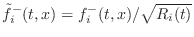
- The normalized wave approach [297] propagates
rms-normalized waves in the waveguide. In this case, each
delay-line contains
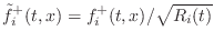 and
and
 . In this case, the power
stored in the delays does not change when the wave impedance
changes. This is the basis of the normalized ladder filter
(NLF) [174,297]. Unfortunately, four
multiplications are obtained at each scattering junction.
. In this case, the power
stored in the delays does not change when the wave impedance
changes. This is the basis of the normalized ladder filter
(NLF) [174,297]. Unfortunately, four
multiplications are obtained at each scattering junction.
- The transformer-normalized waveguide approach changes the
wave impedance at the output of the delay back to what it was at the
time it entered the delay using a ``transformer'' (defined in
§C.16).
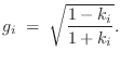
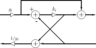
The transformer-normalized DWF junction is shown in Fig.C.27
[432]. As derived in §C.16, the transformer ``turns
ratio'' ![]() is given by
is given by
 |
So, as in the normalized waveguide case, for the price of two extra multiplies per section, we can implement time-varying digital filters which do not modulate stored signal energy. Moreover, transformers enable the scattering junctions to be varied independently, without having to propagate time-varying impedance ratios throughout the waveguide network.
It can be shown [433] that cascade waveguide chains built using transformer-normalized waveguides are equivalent to those using normalized-wave junctions. Thus, the transformer-normalized DWF in Fig.C.27 and the wave-normalized DWF in Fig.C.22 are equivalent. One simple proof is to start with a transformer (§C.16) and a Kelly-Lochbaum junction (§C.8.4), move the transformer scale factors inside the junction, combine terms, and arrive at Fig.C.22. One practical benefit of this equivalence is that the normalized ladder filter (NLF) can be implemented using only three multiplies and three additions instead of the usual four multiplies and two additions.
The transformer-normalized scattering junction is also the basis of the digital waveguide oscillator (§C.17).
Next Section:
Reflectance of an Impedance
Previous Section:
Conventional Ladder Filters


