


Low and High Shelving Filters
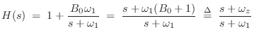
The analog transfer function for a low shelf is given by [103]
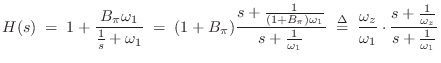
A high shelf is obtained from a low shelf by the conformal mapping
![]() , which interchanges high and low frequencies, i.e.,
, which interchanges high and low frequencies, i.e.,
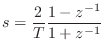
To convert these analog-filter transfer functions to digital form, we apply the bilinear transform:
Low and high shelf filters are typically implemented in series, and are typically used to give a little boost or cut at the extreme low or high end (of the spectrum), respectively. To provide a boost or cut near other frequencies, it is necessary to go to (at least) a second-order section, often called a ``peaking equalizer,'' as described in §B.5 below.
Exercise
Perform the bilinear transform defined above and calculate the
coefficients of a first-order digital low shelving filter. Find the
pole and zero as a function of ![]() ,
, ![]() , and
, and ![]() . Set
. Set ![]() and verify that you get a gain of
and verify that you get a gain of ![]() . Set
. Set ![]() and verify that
you get a gain of 1 there.
and verify that
you get a gain of 1 there.
Next Section:
Peaking Equalizers
Previous Section:
DC Blocker


