


Equivalent Circuits
The concepts of ``circuits'' and ``ports'' from classical circuit/network theory [35] are very useful for partitioning complex systems into self-contained sections having well-defined (small) interfaces. For example, it is typical in analog electric circuit design to drive a high-input-impedance stage from a low-output-impedance stage (a so-called ``voltage transfer'' connection). This large impedance ratio allows us to neglect ``loading effects'' so that the circuit sections (stages) can be analyzed separately.
The name ``analog circuit'' refers to the fact
that electrical capacitors (denoted ![]() ) are analogous to physical
springs, inductors (
) are analogous to physical
springs, inductors (![]() ) are analogous to physical masses, and
resistors (
) are analogous to physical masses, and
resistors (![]() ) are analogous to ``dashpots'' (which are idealized
physical devices for which compression velocity is proportional to
applied force--much like a shock-absorber (``damper'') in an
automobile suspension). These are all called
lumped elements
to distinguish them from distributed parameters such as the
capacitance and inductance per unit length in an electrical
transmission line. Lumped elements are described by ODEs while
distributed-parameter systems are described by PDEs. Thus, RLC analog
circuits can be constructed as equivalent circuits for lumped
dashpot-mass-spring systems. These equivalent circuits can then be
digitized by finite difference or wave digital
methods. PDEs describing distributed-parameter systems can be
digitized via finite difference methods as well, or, when wave
propagation is the dominant effect, digital waveguide methods.
) are analogous to ``dashpots'' (which are idealized
physical devices for which compression velocity is proportional to
applied force--much like a shock-absorber (``damper'') in an
automobile suspension). These are all called
lumped elements
to distinguish them from distributed parameters such as the
capacitance and inductance per unit length in an electrical
transmission line. Lumped elements are described by ODEs while
distributed-parameter systems are described by PDEs. Thus, RLC analog
circuits can be constructed as equivalent circuits for lumped
dashpot-mass-spring systems. These equivalent circuits can then be
digitized by finite difference or wave digital
methods. PDEs describing distributed-parameter systems can be
digitized via finite difference methods as well, or, when wave
propagation is the dominant effect, digital waveguide methods.
As discussed in Chapter 7 (§7.2), the equivalent
circuit for a force-driven mass is shown in Fig.F.10. The
mass ![]() is represented by an inductor
is represented by an inductor ![]() . The driving
force
. The driving
force ![]() is supplied via a voltage source, and the mass
velocity
is supplied via a voltage source, and the mass
velocity ![]() is the loop current.
is the loop current.

As also discussed in Chapter 7 (§7.2), if two physical elements are connected in such a way that they share a common velocity, then they are said to be formally connected in series. The ``series'' nature of the connection becomes more clear when the equivalent circuit is considered.
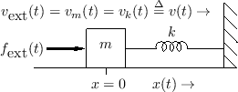
For example, Fig.1.9 shows a mass connected to one
end of a spring, with the other end of the spring attached to a rigid
wall. The driving force
![]() is applied to the mass
is applied to the mass ![]() on the left so that a positive force results in a positive mass
displacement
on the left so that a positive force results in a positive mass
displacement ![]() and positive spring displacement (compression)
and positive spring displacement (compression)
![]() . Since the mass and spring displacements are physically the
same, we can define
. Since the mass and spring displacements are physically the
same, we can define
![]() . Their velocities are
similarly equal so that
. Their velocities are
similarly equal so that
![]() . The equivalent circuit
has their electrical analogs connected in series, as shown in
Fig.1.10. The common mass and spring velocity
. The equivalent circuit
has their electrical analogs connected in series, as shown in
Fig.1.10. The common mass and spring velocity ![]() appear as a single current running through the inductor (mass) and
capacitor (spring).
appear as a single current running through the inductor (mass) and
capacitor (spring).
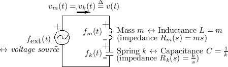 |
By Kirchoff's loop law for circuit analysis, the sum of all voltages
around a loop equals zero.2.13 Thus, following
the direction for current ![]() in Fig.1.10, we have
in Fig.1.10, we have
![]() (where the minus sign for
(where the minus sign for
![]() occurs because the current enters its minus sign),
or
occurs because the current enters its minus sign),
or
Next Section:
Impedance Networks
Previous Section:
Modal Representation


