General Series Adaptor for Force Waves
In the more general case of ![]() ports being connected in
series, we have the physical constraints
ports being connected in
series, we have the physical constraints

The derivation is the dual of that in the parallel case (cf.
Eq.![]() (F.16)), i.e., force and velocity are interchanged, and impedance
and admittance are interchanged:
(F.16)), i.e., force and velocity are interchanged, and impedance
and admittance are interchanged:

The outgoing wave variables are given by
Beta Parameters
It is customary in the wave digital filter literature to define the beta parameters as
where
However, we normally employ a mixture of parallel and series adaptors,
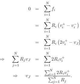
while keeping a force-wave simulation. Since
![]() , we obtain, after a small amount of algebra, the following
recipe for the series force-wave adaptor:
, we obtain, after a small amount of algebra, the following
recipe for the series force-wave adaptor:
We see that we have

Reflection Coefficient, Series Case
The velocity reflection coefficient seen at port
![]() is defined as
is defined as
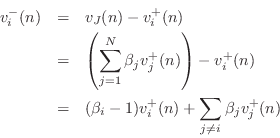
Representing the outgoing velocity wave
where

Equating like terms with Eq.![]() (F.32) gives
(F.32) gives
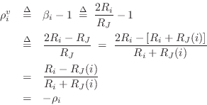
Thus, the
Physical Derivation of Series Reflection Coefficient
Physically, the force-wave reflection coefficient seen at port
![]() of a series adaptor is due to an impedance step from
of a series adaptor is due to an impedance step from ![]() , that
of the port interface, to a new impedance consisting of the series
combination of all other port impedances meeting at the
junction. Let
, that
of the port interface, to a new impedance consisting of the series
combination of all other port impedances meeting at the
junction. Let
denote this series combination. Then we must have, as in Eq.
 |
(F.36) |
Let's check this ``physical'' derivation against the formal definition
Eq.![]() (F.31) leading to
(F.31) leading to
![]() in Eq.
in Eq.![]() (F.33).
Define the total junction impedance as
(F.33).
Define the total junction impedance as


Since

Series Reflection Free Port
For port ![]() to be reflection free in a series adaptor, we require
to be reflection free in a series adaptor, we require
That is, the port's impedance must equal the series combination of the other port impedances at the junction. This result can be compared with that for the parallel junction in §F.2.2.
The series adaptor has now been derived in a way which emphasizes its duality with respect to the parallel adaptor.
Next Section:
``Piano hammer in flight''
Previous Section:
Two-Port Series Adaptor for Force Waves


