


Design a DAC sinx/x Corrector
This post provides a Matlab function that designs linear-phase FIR sinx/x correctors. It includes a table of fixed-point sinx/x corrector coefficients for different DAC frequency ranges.
A sinx/x corrector is a digital (or analog) filter used to compensate for the sinx/x roll-off inherent in the digital to analog conversion process. In DSP math, we treat the digital signal applied to the DAC is a sequence of impulses. These are converted by the DAC into contiguous pulses of length Ts, where Ts is the DAC sample time. The result is that the frequency response of the DAC is not flat; it is rather the Fourier transform of a pulse of length Ts [1, 2]:
$$ H(f)= T_s \frac{sin\left(\pi f T_s \right)}{\pi f T_s} $$
H(f) is called the sinx/x or sinc function. The dB magnitude of H(f) is plotted at the top of Figure 1, were we have ignored the scale factor Ts. The usable range of the DAC output spectrum is normally limited to frequencies less than fs/2. As shown in the middle plot of Figure 1, the sinc function rolls off about 3.9 dB over 0 to fs/2.
This article is available in PDF format for easy printing.
Whether compensation of the sinc roll-off is used depends on the particular application. If compensation is required, we need a function with response that is the inverse of the sinc, as shown in the bottom plot in Figure 1. We’ll call this the goal response. Note that the corrector response need only match the goal response up to the maximum frequency in the DAC spectrum. It is helpful if the maximum frequency is not too close to fs/2 -- this eases the requirements on the corrector and DAC reconstruction filter. The DAC reconstruction filter is an analog lowpass filter that attenuates the images of the sampled output of the DAC.
In a DSP system, the sinx/x corrector is typically placed just before the DAC input, as shown in Figure 2.
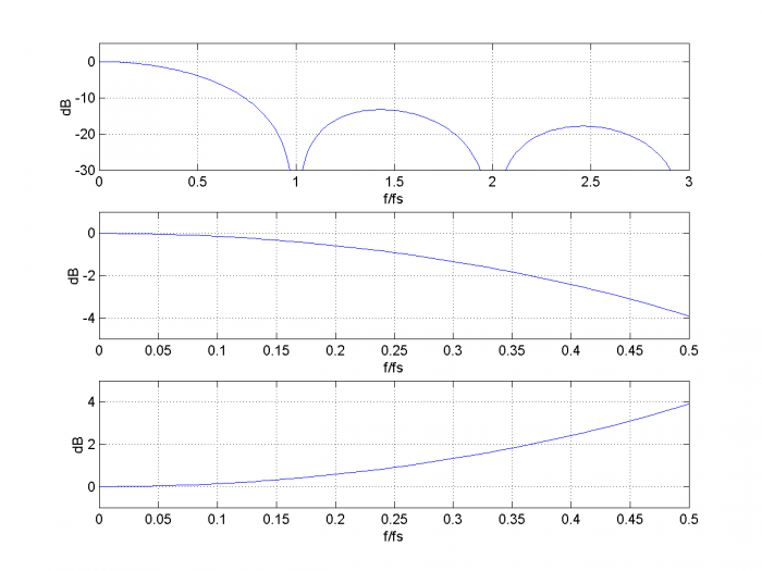
Figure 1.Top: sinc function dB-magnitude response, f = 0 to 3fs.
Middle: sinc function dB-magnitude response, f = 0 to fs/2.
Bottom: Inverse sinc response, f = 0 to fs/2.
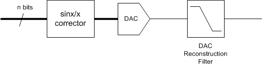
Figure 2. sinx/x corrector in a DSP system.
The sinx/x corrector Matlab function is provided in the Appendix.The function call is:
b= sinc_corr(ntaps,fmax,fs)where:
ntaps = desired number of taps
fmax = maximum frequency of DAC output signal, Hz ( fmax < .499*fs).
fs = DAC sample frequency, Hz
b = vector of sinx/x corrector coefficients
For best results, ntaps should be odd.
Example 1
Let’s design a corrector with ntaps = 5 and fmax = 0.3*fs.The Matlab commands are:
    ntaps= 5;
    fmax= 0.3;
    fs= 1;
    b= sinc_corr(ntaps,fmax,fs)
The output is:
b = 0.0104 -0.0765 1.1331 -0.0765 0.0104
The frequency response of these coefficients is plotted in the top of Figure 3, along with the goal response (see Appendix for the code that computes the responses). The vertical red line is at f = fmax. The overall response of the DAC plus sinx/x corrector is shown in the bottom of Figure 3. The ripple of the overall response is less than +/- .015 dB.
Note that the gain of the sinx/x corrector is 1.164= 1.32 dB at f= fmax. Thus, at the corrector input, the peak-to-peak signal level of a sinewave at fmax should be backed-off 1.32 dB from full-scale to avoid clipping. A simple way to achieve this is to incorporate a gain of 1/1.164 = 0.859 (or less) into the corrector. For example, incorporating a gain of ¾ would work.
Example 2
In this example, we keep ntaps = 5, but extend fmax to 0.375*fs. The resulting coefficients are:
b = 0.0164 -0.0872 1.1451 -0.0872 0.0164
The frequency response is plotted in the top of Figure 4, along with the goal response. The overall response of the DAC plus sinx/x corrector is shown in the bottom of Figure 4. The ripple of the overall response is roughly +/- .05 dB.
The gain of the sinx/x corrector is 1.269= 2.07 dB at fmax.
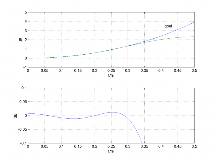
Figure 3. sinx/x corrector with fmax= 0.3*fs and ntaps= 5.
Top: Goal response and sinx/x corrector response.
Bottom: Overall response of corrector plus DAC.
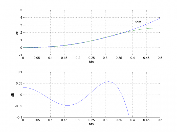
Figure 4. sinx/x corrector with fmax= 0.375*fs and ntaps= 5.
Top: Goal response and sinx/x corrector response.
Bottom: Overall response of corrector plus DAC.
Fixed-Point Implementations
The function sinc_corr generates floating point coefficients. We can convert them to a decimal representation of fixed-point using:
b_fix= round(b*k)/k;
where b are the floating-point coefficients and k is 2 raised to an integer power. When quantized with k= 512, the coefficients of Example 1 become b_fix = [5 -39 580 -39 5]/512, and they produce the overall response shown in Figure 5.
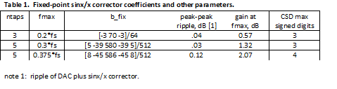
Table 1 lists coefficients and other filter parameters for three fixed-point sinx/x correctors. The coefficients’ maximum number of signed digits is listed for Canonic-Signed-Digit (CSD) implementations [3].
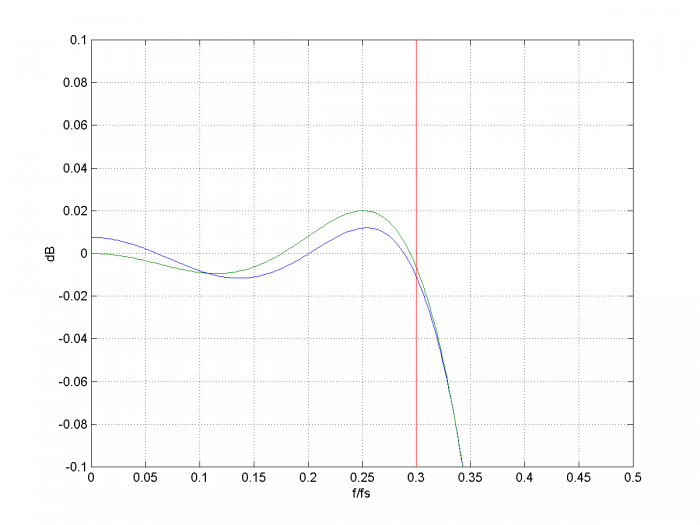
Figure 5. sinx/x corrector with fmax= 0.3*fs and ntaps= 5.
Overall response of corrector plus DAC.
blue = floating-point coefficients. green= fixed-point coefficients with k= 512.
References
1. Smith, Steven W., The Scientist and Engineer’s Guide to Digital Signal Processing, California Technical Publishing, 1997, Ch 3 (p 44 – 48) http://www.dspguide.com/
2. http://www.ee.cuhk.edu.hk/~wkma/engg2310/handouts/2-fourier.pdf
3. Robertson, Neil, “Canonic Signed Digit (CSD) Representation of Integers”, Feb, 2017 https://www.dsprelated.com/showarticle/1030.php
Neil Robertson July, 2018
Appendix Matlab Function sinc_corr
This is a Matlab function to find the coefficients of a linear-phase FIR sinx/x corrector. It uses the Matlab firls function for least-squares FIR design. Note: the number of taps (ntaps) should be odd for best results.
    % sinc_corr.m  7/20/18  Neil Robertson
    % function synthesizes FIR DAC sinx/x corrector
    % ntaps       number of FIR taps.  Should be odd.
    % fmax     Hz maximum frequency to be corrected.  Require fmax < .499*fs
    % fs       Hz  DAC sample frequency
    % b            vector of FIR coefficients
    function b= sinc_corr(ntaps,fmax,fs);
    if fmax >= .499*fs
        error('fmax must be less than .499*fs')
    end
    %
    npts= 8;                % number of freq points for goal function
    k= 0:npts-1;
    f= k*fmax/(npts-1);                          % Hz
    hsinc= sin(pi*f/fs)./(pi*f/fs + eps);        % sinx/x response
    hsinc(1)= 1;
    h_goal= 1./hsinc;                            % goal function
    %
    % least-squares FIR design
    ff(1:2:2*npts-1)= 2*f/fs;                  % f/fnyquist  vector of freq pairs
    ff(2:2:2*npts)= 2*f/fs + .001;
    a(1:2:2*npts-1)= h_goal;                   % vector of amplitude goal pairs
    a(2:2:2*npts)= h_goal;
    %
    b= firls(ntaps-1,ff,a);                    % corrector coeffs
.
Here is the Matlab code for generating the plots in Figures 3 or 4:
    b= sinc_corr(ntaps,fmax,fs);
    [hc,f]= freqz(b,1,256,fs);
    Hc= 20*log10(abs(hc));                      % dB sinc corrector freq response
    hsinc= sin(pi*f/fs)./(pi*f/fs + eps);
    hsinc(1)= 1;
    Hsinc= 20*log10(abs(hsinc));                % dB DAC freq response
    Htotal= Hc + Hsinc;                         % dB Overall freq response
    %
    subplot(211),plot(f,-Hsinc,f,Hc,[fmax fmax],[-1 5],'r'),grid
    axis([0 fs/2 -1 5])
    xlabel('f/fs'),ylabel('dB')
    text(.41,3.5,'goal')
    subplot(212),plot(f,Htotal,[fmax fmax],[-1 1],'r'),grid
    axis([0 fs/2 -.1 .1])
    xlabel('f/fs'),ylabel('dB')
- Comments
- Write a Comment Select to add a comment

Nice write-up Neil! See the posting at the link below detailing the 3 tap symmetric FIR solution I often use for Sinc correction, making note that the Sinc funciton is approximately cos(x) in the first half of the main lobe, so I compensate with coefficients that would produce a raised cosine in the frequency domain: https://dsp.stackexchange.com/questions/19584/how-...

Hi Dan,
I like your simple solution for a three tap design.
Regards,
Neil
Thanks Neil, and to note it doesn't replace your optimized solution for when a better match is required (or when the decreased stop band rejection is of concern), but wanted to share for the cases when "good enough" is sufficient. Cheers and good work!
I am writing about Sampling theorem. In sampling delta pulse train is used. If we take fourier transform the transformed value should be unity . How we get sinc function ?
Hi Netloce,
Yes, we treat the signal samples as impulses. This is a choice that makes the math work. However, when we convert the digital signal to analog, we have to deal with real-world DAC's. The DAC output consists of rectangular pulses of length Ts, which gives rise to the sinc response.
We are in effect considering the DAC input to be impulses, and its output rectangular pulses.
Does this make sense to you?
regards,
Neil
you see the equation of sampling theorem? Why a(n) is the convolution of W(n) with sinc function ? a(n), I guess , is the weighting factor.
Hi Neil
I have been following your solutions , and very interesting.
I wander if you can provide me a guidance for the following
I have used Matlab firpm() function to design target x/sinx
and it works if it is applied on the real signal before the DAC .
where y = Ix*cos(2*pi*fc*t) - Qx*sin(2*pi*fc*t)
Ix and Qx are QAM symbols (interpolated to DAC speed through interpolation filters)
And then DAC input is
dac_in =y * h_x_sinx
However,this circuit flattens the entire range from DC to DAC Fs.
I like to do the x/sinx in baseband and
such as
I +jQ - > h_x_sinx -> Interpolation Filter -> DAC input
I thinks I need to use some sort of h_x_sinx filter coefficients
that need to be complex ?
If you know, what other methods one can do to do the x/sinx
in baseband
Regards
kdinc
Hi kdinc,
Depending on the bandwidth of the signal, It could be possible to do the following:
I + jQ --> quad mod --> interp --> sinx/x corr --> interp_by_2 --> DAC
I don't know if it would be possible to do sinx/x correction at baseband.
regards,
Neil
To post reply to a comment, click on the 'reply' button attached to each comment. To post a new comment (not a reply to a comment) check out the 'Write a Comment' tab at the top of the comments.
Please login (on the right) if you already have an account on this platform.
Otherwise, please use this form to register (free) an join one of the largest online community for Electrical/Embedded/DSP/FPGA/ML engineers:


