


fractional delay filter for non real time applications
 Started by 4 years ago●14 replies●latest reply 4 years ago●390 views
Hi guys,
I would like to create fractional delay filter that can be applied on a signal for non real time applications. My approach is to apply a linear phase shift via a multiplication of a ideal filter (rectangular window) with linear phase in the frequency domain. In the next step, I transform the signal back to the time domain using a symmetric ifft to obtain a real valued signal.
The Matlab code looks like this:
N = 1e3; % number of samples

n0 = 0.3; % fractional delay in integer samples

x = randn(1,N); % time domain signal

X = fft(x); % frequency domain

k = 0:N-1; % frequency index vector

Y = X.*exp(-1i*2*pi*k/N*n0); % linear phase shift wrt to frequency

y = ifft(Y,'symmetric'); % back to time domain
Due to the rectangular window of the filter I will get ringing artifacts the frequency boundaries. Nevertheless, is this a valid approach to delay a signal by a fractional integer delay?
Cheers,
Jakob

The ringing you refer to is because your approach creates a filter frequency response which has a discontinuity. I'm using the word discontinuity incorrectly because we are in sampled time, but the point is that your linear phase changes abruptly at the transition between the highest frequency and the zero frequency. For a non-fractional delay, the discontinuity is a multiple of 2 *pi which is OK since the phase is an angle and angles are normally mod 2*pi.
Most people would place that discontinuity at the half-sampling frequency rather than at zero, but I'm not sure that isn't just a matter of taste. But discontinuity in the frequency domain always leads to a Gibbs phenomenon in the time domain and to avoid that you should probably apply a time domain window. That means that the signal you are delaying is the windowed signal.
does this mean, that the approach I showed leads to Gibbs phenomenon but yields perfect linear phase for the whole band with no group delay error?
For my application I need a very precise delay filter (<10⁻4 wrt to the sample interval). The amplitude response isn't that important to me.
Does this make sense?
I think you have to express your requirement more carefully. What exactly is a precise delay filter? If the input and the output of the filter have the same sampling rate then you need a precise definition of what you mean by a delay.
Let's do a thought experiment. Say you have a random number sequence X that is a million samples long, where the assumed sampling rate is 1 microsecond. Now select every ten-thousandth sample, samples 0,10000,20000,..., and store it in another file Y. Imagine some process that creates a 100 sample output file Z which duplicates a different set of samples which is identical to the original million sample sequence X at samples 5,10005,20005,...
Clearly you can't expect to do that with truly random samples.
So instead, start the million sample sequence with a constrained set. One way to constrain it would be to take X's DFT and zero out most of the samples, keeping only DFT bins 0 to 49, and their mirror values -1 to -49 (mod 1 million). The inverse FFT is a million sample sequence X' with only frequency components between +/- 49 Hz so it can be sampled with 100 samples without violating the Nyquist sampling criterion. In other words it should be possible to recover the whole set of a million samples of X' from 100 samples Y'. You just need to put the 100 samples into a million spaces with all the other 999900 spaces having zero, and then convolve it with h(n)= (sin Nn)/ sin n. The result of the convolution is a million sample sequence Z' which matches X' everywhere. But you don't want it everywhere so you don't need to compute all the points of the convolution everywhere, only at points 5,10005,20005, etc.
That's your baseline reference for what you mean by a delay.
Now I think it is fair to assume that your original X and its reduced bandwidth X' were both real sequences. Real sequences have Fourier transforms with with real-part even and imaginary part odd.
The scheme you proposed will give Z' with some imaginary part. That, at a minimum, represents an error introduced by your technique. By Parseval's theorem the total energy of the output is the total energy of the input so there must be another part of the error in the real part.
How would you modify your scheme to eliminate any imaginary part? You have to multiply the transform by the transform of another real sequence, which has the required symmetry. In other words, let the linear phase function have its break at the folding frequency rather than at frequency 0.
That eliminates the imaginary part, which is all error. But it's not going to reproduce Z' at the desired 100 points. To do that you need to preserve ALL the frequency components, and the Gibbs phenomenon will produce ringing which is strongest near the phase discontinuity at 50 Hz.

you need to zero-pad your x signal before the FFT. delaying the signal by linear phase-shifting the spectrum is exactly an example of using the FFT to do what we sometimes call "fast convolution". now this assumes non-real-time.
for real-time, if you have memory for a large table, i might recommend using a Kaiser-windowed sinc() function and then linear interpolation between the subsamples. Farrow is okay for what it is, but it is limited to Lagrange interpolation, which is a specific polynomial-based interpolation.
This isn't accurate. The Farrow structure is generic and can implement any polynomial type and order. The coefficients determine which polynomial is implemented: Lagrange, hermite, spline or even custom designed to meet given time domain or frequency specifications.
You are absolutely correct. I was reverberating what I read at https://ccrma.stanford.edu/~jos/Interpolation/Farrow_Interpolation_Features.html and I didn't drill in enough to see that it could be any polynomial. But it does have to be a polynomial-based interpolation and I am not sure how easily you can jump over integer sample boundaries using this Farrow structure.
As for me, since all of the applications I have ever done fractional delay could easily provide an 8K word lookup table, I just designed the bestest brickwall FIR filter I could with 32-taps and 512 phases (or fractional delays) and use linear interpolation between adjacent fractional delays. Reasonably efficient (64 MACs plus one more for linear interpolation) and clean as a whistle. And I could jump to whatever precision delay (as long as it was at least 15 samples) I wanted to every single output sample.
Farrow is just generic structure for implementing polynomials (including linear interp).
Now the frequency response of polynomial based filter doesn't improve much for order >=3 so adding a fixed filter prior to farrow is a good idea instead of cranking up the order.
From memory, good fixed filter up by 128x followed by linear interp was about the same as a good 8x followed by cubic (100dB ish image/alias attenuation). Looks like this is in-line with what you are saying.
What is best mostly depends on the hardware.

RBJ-
That's interesting Farrow has that limitation.
Everyone calls out Farrow anytime decimation/interp factors are impractical or other reason fractional resampling is needed. It's like a reflex. I didn't hear about any drawbacks until now. Thanks.
-Jeff

As others have said, you can do it in the time domain. You could use a Farrow interpolator, or for better accuracy of the amplitude response, you could use a Fractional-delay FIR. See my article on Fractional Delay FIR at:
https://www.dsprelated.com/showarticle/1327.php
regards,
Neil
thanks Neil, that is very valuable for me!
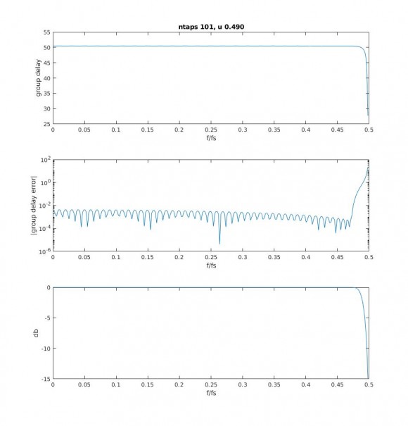
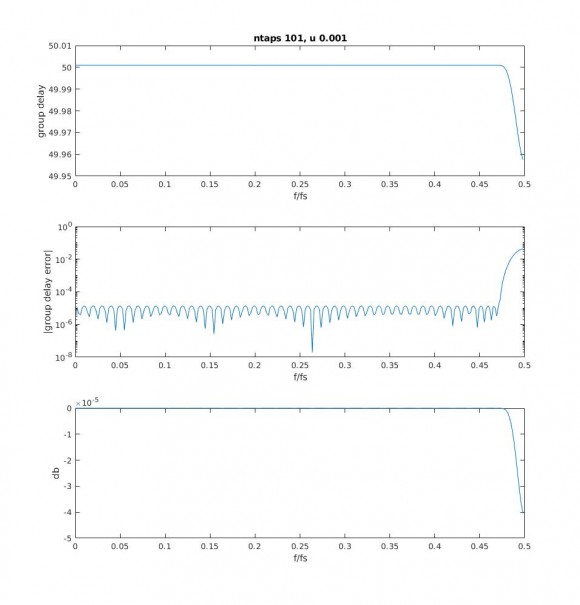
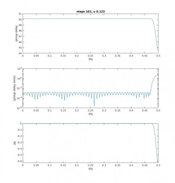
I checked out your scripts and had a look at the group delay error (magnitude of input group delay minus output group delay). The error lies at around 10⁻3 for a fractional delay of 0.123. The error increases with increasing fraction delay.
Do you know how I could create a fractional delay filter that has an error below 10^-4?
Hi JGruber,
You can try changing the dB ripple parameter "r" of the Chebychev window in my function. It is set at 70 dB -- you can improve accuracy by using a higher value, e.g.:
win= chebwin(ntaps,80);
For a given FIR order, as you increase r, the delay ripple decreases at the expense of reduced bandwidth of the filter.
Another option would be to use a Farrow interpolator (piecewise polynomial interpolation), which would give flat, accurate group delay, although the amplitude response is not perfectly flat.
regards,
Neil
Thank you very much Neil.

Hi,
fft then ifft is very expensive for that. I will just use farrow resampler.
Hi,
If you need to vary the fractional delay real-time, farrow resampler is a good choice. If you can afford to recompute the coefficients for each different fractional delay, a sinc interpolation filter could also work. (essentially, the time domain equivalent of your FFT approach).


