


PLL jitter and double-sideband suppressed carrier demodulation
Hi everyone,
I want to demodulate a double sideband modulated signal with suppressed carrier. There is a reference signal with the same phase than the suppressed carrier but different frequency so I need a PLL.
As I had to do the PLL from scratch, I started from an analogue PLL so as to have it working before doing any optimisation. The PLL consists of an XOR phase detector and an RC first order filter that then goes into a “VCO”. The filter’s fc and the VCO’s Kv are adjustable so as to find the right parameters for it to lock. The VCO sine output is generated using the sine function from the math library (horrible in CPU, I know, but quick for proving the concept).
I have tried also another PLL based around DDS (direct digital synthesis) instead of sine functions, which improves the CPU use a lot. Notwithstanding, DDS creates spurs due to the phase quantisation and I need quite many points in the sine tables to get enough SFDR. Unfortunately, there is not much of an improvement in the demodulation performance.
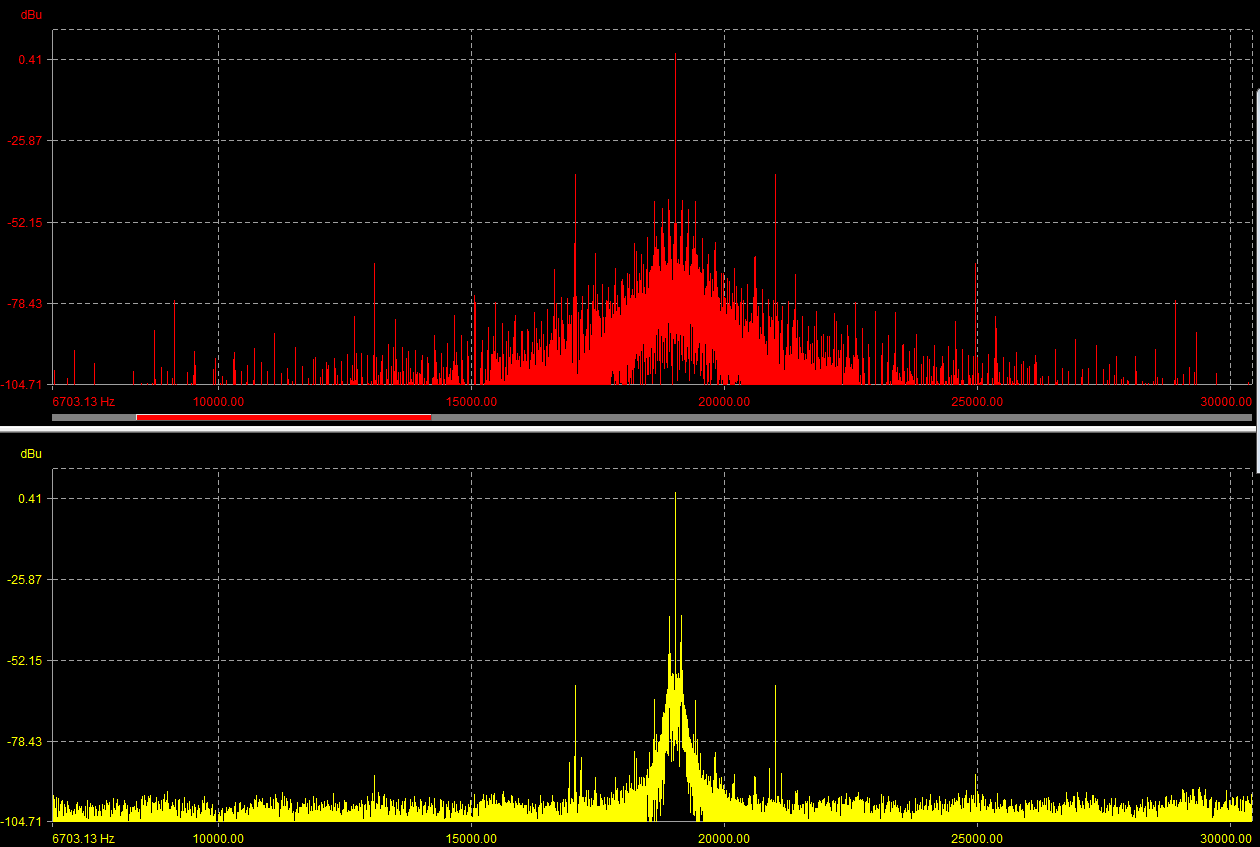
I have used an audio analyser to see the spectral purity of both PLL solutions. The one in red is the “analogue” PLL whilst the yellow is a DDS based solution,
The reference signal I’m synchronising to is (should be) static apart from tolerances in its generation or the clocks of the systems involved. Thus, I do not really need to have much bandwidth or speed to lock. For that reason, I try to keep the filter cutoff frequency and Kv (VCO gain) with values as low as possible that keep the PLL locked.
The signal I am synchronising to is a pure spectral line down to the noise floor. Notwithstanding, the spectrum of the PLL signal is quite far from being pure; the base is quite wide, what means there is quite a lot of jitter. This results in a demodulated signal that does not meet the specs.
Can anyone help with this? Is there any other way to reduce the jitter? Different filter/order/etc? Any help is welcome, thanks.
Hi konejisimo,
Sounds like your input reference is very clean, so the jitter is likely being introduced by the PLL. Noise injected at the VCO's input (tuning voltage node) is high-pass filtered by the loop. Try increasing the loop's bandwidth so the loop can "correct" this noise before passing it out.
You might also try a classic loop filter as shown in (a) in the following link.
http://www.designers-guide.org/Forum/YaBB.pl?num=1...
The capacitor to ground is smaller than the capacitor in series with R, and is used to remove higher frequency ripple on the tuning voltage node. There should be a lot of info available for this filter online. Some quick links I found:
https://electronics.stackexchange.com/questions/30...
http://fsl.narod.ru/PLL/pllfilterprogram.htm
The Laplace math is pretty easy to work through if you want to do a behavioral model, although you could probably find it analyzed somewhere online as well.
Good luck, Gary
Hi Gary,
Thank you for your answer.
The reference is very clean as it is digitally generated in another device. My analogue PLL is implemented in a DSP.
As the signal from the XOR function is a square wave so my thinking was filtering out anything above DC or some Hz to have as little fluctuations in the VCO controlling “voltage” to have a steady frequency. That is why I was asking if a higher order filter would work better. The choice of an RC was because it was easily discretized whilst keeping the possibility of adjusting its cutoff in real time.
So the process I followed to tune the PLL parameters was to choose the smallest fc possible and starting from 0 Hz/V VCO gain increased the gain until locked.
I played a little with the values of fc and Kv to see if it improved the capture and hold-in ranges but anything above the minimum values I found to lock the PLL were resulting either in the widening of the base of the generated frequency (jitter), increase of the noise floor or sidebands around the generated tone.
Due to my observations, I was surprised by your statement “Try increasing the loop's bandwidth so the loop can "correct" this noise before passing it out.” as increasing the fc was not helping at all.
Won´t the loop bandwidth be (mainly) determined by the filter´s fc and gain to the VCO? Also, if the fc is higher… there will be more harmonics going through the filter into the VCO
Notwithstanding, when I have some time I will try discretizing the filter you have posted and give it a go.
Thanks.
It depends on the source of the noise. If the output jitter is dominated by the VCO, increasing the loop bandwidth helps filter this out (since jitter injected by the VCO gets high-pass filtered by the loop). If generated elsewhere, it gets low-pass filtered by the loop (so reducing the loop bandwidth is the way to go).
Here's a nice reference for an analog PLL's math (slides 8-10): http://pallen.ece.gatech.edu/Academic/ECE_6440/Sum...
If raising the loop bandwidth made things worse, try optimizing the other components (e.g. loop filter, PD) as others suggested below. The closed-loop bandwidth should be less than the input reference frequency for stability concerns.
Hi Gary,
I will give a go first to the better phase detector option but I will also try your suggestions.
By the way, thanks for the link, it seems a quite interesting document.

Konejesimo,
Here are posts I wrote on digital PLL design that you might find useful:
https://www.dsprelated.com/showarticle/967.php
https://www.dsprelated.com/showarticle/973.php
Using an XOR gate as a phase detector is not optimal; it creates a lot of noise because the output is always bouncing between "high" or "low". It is better to use a phase detector that has a "0" output. In the case of an analog PLL, this means "low", "high", and "high-Z". For a digital PLL, the output can be a signed integer.
regards,
Neil
Hi Neil
Thanks for your answer. And great articles, thanks!
I have checked your articles and I see that you use the reference phase as an input to the phase detector but that is unknown. I guess I can use the arcsine function with some CPU penalty. Obviously, the arcsin expects an input signal with amplitude 1 but the the reference signal amplitude is also unknown so I will need to implement some sort of AGC. Hopefully the amplitude will be steady enough so there is no amplitude modulation that will result in some phase error after the arcsine (but hopefully smaller than the noise coming from the XOR?) Does it make sense or is there a better way to find the phase? Please, confirm and I will definitely try your solution.
About the phase detector, capture and hold-in ranges considerations apart, would then a multiplier be better for the analogue version in terms of the generated noise (as the signals won´t be square waves)?
In the analogue PLL I use -0.5 and 0.5 as outputs. I don't know how would I translate your suggestion that into code (0 output?) When would that High-Z happen? And how would it be with the signed integer?
In my digital PLL implementation, the XOR gate does not give a straight high or low. It increments or decrements a phase error variable (pe) that is accumulated for some given period. When that integration period expires, the new phase and frequency are calculated as follows:
Osc_phase = osc_phase (n-1) + K1 * pe
Phase_incr = Ph_incr (n-1) + K2 * pe
Then in every loop iteration the osc_phase = osc_phase (n-1) + phase_incr (n-1)
Regards
Konejisimo,
I don't want to make specific suggestions that may be totally off the mark for your situation. A couple of possibilities for phase detectors in an all-digtial design are Hilbert transformer followed by arctan, or a Time-to-Digital Converter. I have seen the arcsin mentioned in a paper, but I don't know the pros and cons.
Note the phase detector output in my blog post is signed-integer (i.e. fixed-point), and the output is zero when locked.
For an analog PLL (actually analog/digital), the usually preferred method is the phase-frequency detector (PFD), but that assumes a digital input. The PFD drives a charge pump that goes to high-Z when the phase is locked, then occasionally pulses high or low to keep itself locked. This is how frequency synthesizer chips work.
regards,
Neil
Hi Neil.
First of all, thanks for your answer and apologies for the delay in answering back. I wanted to have something meaningful before answering but I cannot put more time into it as I had to move to some other projects…
I did some trials though and wanted to share the results:
Phase recovery based in ASIN.
The asin(x) function is several hundred times faster than calculating the sin(x). Obviously this makes it attractive but the problem as I foresaw, is that asin will only work with a perfect 1.0 amplitude sine. Any difference in amplitude makes it unusable.
Regenerating a sine with the same phase than the reference works perfectly. If the amplitude is different, using a peak meter to normalise it to 1 works also fine. The problem is that any signal will have some noise and the smallest noise means that the recovered phase will make some jumps that render the recovered signal unusable (the BW of the signals expands greatly every now and then). Using an RMS meter to smooth out the noise gives even worse results.
QUESTION 1: Has anyone used something like this with success? Or maybe can point to any paper/website?
Phase recovery base in Hilbert transform + atan.
I tried this method in Matlab (octave actually). As far as I am aware, the function finds the hilbert transform by eliminating the negative frequencies of the FFT and then calculates the IFFT. As I need something super light in terms of CPU load so I cannot use that approach. I used two different programs to generate coefficients for a Hilbert transform filter. I tried the filter in Octave and, providing that the filter delay and amplitude is compensated, the filter seems to be working fine. Problems in the delay or amplitude create increasingly non linear phases (easy to spot)
For some reason, when I try it on the DSP, I get very strange results. I can get the phase and looks linear but it is tilted in a way that is not usable (or not easily).

I have tried several filter lengths but the result is the same.
QUESTION 2: Could anyone guess what the problem might be?
Time-to-Digital converter.
I saw some documents and it seems it is used strictly in HW and I could not find any reference as to be used in SW. I don’t know if it would be the best approach.
QUESTION 3: What are your thoughts?
--------- OTHER APPROACHES DIFFERENT TO A PLL ---------
Zero crossings and resyncing (as a substitute for a PLL)
I was thinking maybe another approach could be averaging a big amount of (interpolated) zero crossings to get the reference frequency and once locked in frequency synchronise the phase on another zero crossing. Then allow for smaller corrections. But I do not know how well would this perform.
QUESTION 4: Can anyone see this going anywhere? Any foreseeable problems?
Pilot squarer.
The signal I need for demodulation is precisely double the frequency of the pilot but with the same phase. I tried a pilot squarer because of the trigonometric relation
sin(alpha) = 1/2 * (1 - cos (2alpha))
After normalising the amplitude and removing the DC term, the signal was as pure as the reference and the amount of CPU use negligible. Compensating for the delays of the pilot extracting filter and the algebraic operations It worked like a charm but the problems came when trying to demodulate real signals.
The problems are that the filter to extract the pilot has to be very narrow. Otherwise, the undesired noise was going to be modulated by the pilot squarer, needing an extra filter afterwards. Also as the filters are narrow, the phase delay changes with the pilot frequency (that depends on the transmitter and receiver clocks). Too many problems and too much processing for a simple thing.
QUESTION 5: This was abandoned very early in favour of a PLL based solution. Any comments are welcome because maybe you can spot something I did wrong.
I really like the Hilbert transform approach as that would allow me to use the PLL from your articles straight away.
PS:
QUESTION 6: Is there any other approach I could pursue? I think I do not have many more ideas.
I will also reply to Gary Giust and Tim Wescott when I have more time
Thank you everyone

Most important: You can look at the command to the VCO to get an idea if the problem is the spectral purity of the VCO itself or if you're giving it a noisy command. If you don't know the problem, you can't solve it. I'd look at the signal from the phase detector, too -- for a spectrally pure VCO running close to the reference frequency, it should be spectrally pure around DC.
Less important, but it still matters: You're using an XOR detector, but that's a Bad Thing in a sampled-time system; it introduces far more noise than it would in a continuous-time system. You may find you need to bite the bullet and get two sines out of your VCO, one at the reference frequency and one at the carrier frequency.
Hi Tim,
I will definitely look at the output of the phase detector and after the filter in the analogue version.
In the digital PLL I do not use the output of the XOR straight, I have explained in a response to Neil´s post, so checking the phase detector and filter signals it can probably be less informative or difficult to do.
What alternative are you suggesting to the XOR gate?
Thanks
You need to multiply by a sine wave of the appropriate frequency. This is a downside of sampled-time control. Using an XOR effectively means that you're multiplying by a square wave -- this is OK in continuous-time, but when you sample a square wave (which you're implicitly doing by using an XOR), the aliasing effects are all lined up against you.
You may be able to multiply by a triangle wave if a sine wave is really too much -- but I suspect that you'll only reduce the bad effects of aliasing, and probably not enough to make it worthwhile.


