


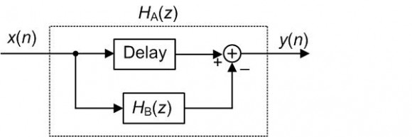
I have a vague memory of sometime in the past encountering a digital filter block diagram like the following
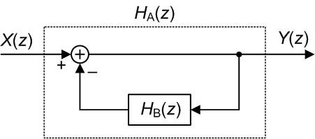
accompanied by text stating something like:
[1] If H_B(z) is a lowpass filter, then the overall H_A(z) filter is a highpass filter;
or
[2] If H_B(z) is a bandpass filter, then the overall H_A(z) filter is a bandstop (notch) filter;
Have any of you ever encountered the above diagram accompanied by text similar to statements [1] or [2]?
Sure I have. I first encountered something like it when I was trying to educate myself about analog techniques, back in the 1950s. For now, forget the math. When certain frequencies are selectively fed back in a negative-feedback loop, the net effect is that they are suppressed in the output. Do you need more detail? If need be, I can still do the math.
Regards,
Jerry

Hello Jerry,
I can easily believe that the above process might be used in the analog world. But my question was about a digital implementation.
PS. If you are the Jerry that once spoke to Albert Einstein in a phone conversion, then I say, "Hi Jerry. I hope you're doing well!"
[-Rick-]
Yes. Rick, I'm the very Jerry you once had a beer with out in California. This isn't a social medium, so I'll keep it short. I'm in reasonably good health. but my need for twice-weekly dialysis makes travel difficult. Be well!
Back to business. If HsubB(Z) in your diagram has useful frequency selectivity, it will probably have a long impulse response. I don't off hand see the point of a single digital component designed this way, but it might be an easy way to create a response complementary to one already designed. In the analog world, frequency selective feedback both shapes the frequency response and reduces non-linearity distortion. (Think feedback tone controls.)
Jerry
Long time since I tuned into a channel with you in it, Jerry. Glad you're still kicking. I'm 71 now and kicking too. Working harder than ever but DSP is a small side of it now.
You may remember me as Bob Cain from comp.dsp but this is who I am now.
It was a long time back, but the name is familiar. I sort of dropped out without really intending to. Stephane seems to have drawn me back, and I thank him for it.
Jerry
Hello Rick,
This is very interesting questions and answers. I was wondering what you meant by "digital implementation"?
Does that mean you are looking for impulse response or transfer function to implement the filter?
If not, what would you need?
Thanks everyone for your educational comments.
Best regards,
Shahram
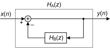
Hello Shahram, by "digital implementation" I mean: computing the y(n) output sequence, from the following filter, given the x(n) input sequence.
Thanks Rick.
Happy 4th
Shahram
Hello Rick,
Intuitively, it makes sense.
For instance, in case of LPF in the negative feedback; the low
frequencies are subtracted from incoming, all frequencies, therefore only high
pass frequencies would make it to the output.
Obviously, a rigorous mathematical formulation has to be done to drive
that properly either in the time/impulse response or frequency domain/transfer
function.
Best regards,
Shahram

Hi Rick,
No I have not seen that structure -- I have seen feed-forward structures for that purpose.
The transfer function of your structure is of course Ha = 1/(1 + Hb(z)). So if Hb were a FIR filter Hb = [b0 b1 b2 b3], then Ha = 1/(1+b0 + b1z^-1 +b2z^-2 + b3z^-3). I don't think this will create a complementary filter in general. It doesn't seem to work for b = [1 1 1 1]/4, but maybe I made a goof.
regards,
Neil
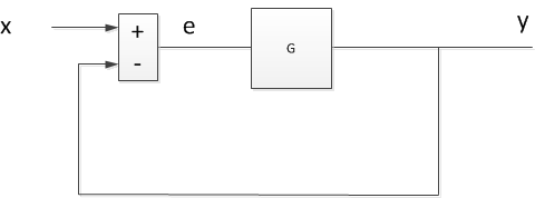
P.S. For the system shown below, if CL = Y/X = G/(1+G) is lowpass, then e/X = 1 - CL is the complementary highpass function.
This comes up in PLL analysis. For PLL's, the e/X response is the phase error relative to the reference phase, and it is a high-pass response.
Hi Neil,
It's easy to fall into the trap of thinking that the zeros (poles) of H_B(z) become the poles (zeros) of the H_A(z) filter. But that's not true as you have shown here.
The reason I asked my original question is because I don't think the H_A(z) filter in my diagram can, in general, be implemented as a digital filter. I'm also thinking that the system in your diagram cannot be implemented as a digital (discrete samples) system. I say that because given 'x' in your diagram, to compute 'y' we first need to compute 'e'. But to compute 'e' we need to know the value of 'y'.
(What's interesting to me, Neil, is that I've have seen block diagrams like my diagram and your diagram in published IEEE papers.)
Rick,
As a practical matter, if the sample rate is much higher than the filter passband, you could insert a delay of one sample in the block diagram without affecting the response. That would allow it to be realized as a digital system.

As long as your \( H_B \) is proper in \( z \) (by which I mean the order of the numerator is strictly less than the order of the denominator) you can, indeed, implement your \( H_A \).
But in the general case where the numerator and denominator of \( H_B \) both lead with \( z^N \) then you have an impossible situation (or at least one where you have to start by doing some algebra before proceeding on to implementation).
I think you're interpreting Neil's results incorrectly.
$$ H_B \left( z \right ) = \frac{b_0 z^3 + b_1 z^2 + b_2 z + b_3}{z^3} $$
Then \( H_A = \frac{1}{1 + H_B} \) gives (after some reduction)
$$ H_A \left ( z \right ) = \frac{z^3}{ \left( 1 + b_0 \right) z^3 + b_1 z^2 + b_2 z + b_3} $$
Clearly, \( H_A \) has a triple zero at \( z = 0 \), to match the triple pole at \( z = 0 \) possessed by \( H_B \).
Hi Neil, to elaborate on my "fall into the trap" comment:
For example, if your 'b' coefficients are [1,1,1,1] then H_B(z) has zeros at: -1, +j, and -j on the z-plane. And H_A will have poles at: 0.12 + j0.814, 0.12 -j0.814, and -0.74 on the z-plane. Thus the poles of H_A(z) are not equal to the zeros of H_B(z).
Actually, \( S = \frac{e}{X} \) comes up in all closed-loop dynamic systems analysis -- it's the sensitivity function, from which all sorts of useful facts about the system can be determined (not least of which is the system's sensitivity to injected noise at any given point).
This mostly rehashes what Jerry is saying.
No, possibly not that exact diagram, but yes, that principle is pretty well known in dynamic systems circles. (Now watch someone find something that I've written saying that...)
Because of how I define "high pass", [1] is a misstatement IMHO. In fact,$$ H_A \left ( z \right ) = \frac{1}{1 + H_B \left ( z \right)} $$
This means that the poles of \( H_B \) become the zeros of \( H_A \). To my mind, a filter is only high-pass if it has a zero at \( f = 0 \) so \( H_A \) is only high-pass if \( H_B \) has at least one pure integrator. Notch filters don't always have infinitely deep nulls so you can get by with [2], but for the ultimate in nulls \( H_B \) needs to have a resonant pole pair sitting on the unit circle.
I'm not sure if there's any utility to this in DSP (well, some, in that [1] forms the basis for really accurate and compact DC blockers), but [1] is the basis for the integrator in a PID controller, and I could see [2] being used if you needed zero error at some specific frequency (a resonant sigma-delta, maybe?).
Hello Tim,
I was wondering if you have any reference material that covers the theory behind this topic?
if so, would you point me to that?
Happy 4th,
Shahram
Hey Shahram:
I don't know if there are any references that really rub your nose in it, but just about any introductory book on closed-loop control will have that result.
Even (and thank you for the opportunity for a shameless plug!) mine: http://wescottdesign.com/actfes/actfes.html
The way that I like to think about this when I'm trying to understand it intuitively is that at those values of \( z \) where the open-loop gain goes to infinity, the closed-loop sensitivity (which is what your \( H_A \) is) absolutely must go to zero.
Thanks for response, Tim.
Shahram

Hi Tim,
if you want to inline equations, simply surround them with
\( ... \)instead of
$$ ... $$
Your text is readable the way it is right now, but I though you might find the tip useful down the line..
Thanks!Thanks Stephane. You'll note that I've edited my post -- it looks much better now.

Agreeing with everybody else, I am using something like that in a project now. It's a moving average filter which is then subtracted from the input to remove the DC offset. By changing the filter length I widen the notch from DC, and it gives a lot of control over what very low frequency gets removed. The moving average filter is lowpass, the result is highpass.
Dr. mike
But it sounds like you're implementing something more like this:
where the zero in \( H_A \left ( z \right ) \) will occur at those values of \( z \) where \( H_B \left ( z \right ) = 1 \), rather than at those values of \( z \) where \( \lim_{ \zeta \to z } H_B \left ( \zeta \right ) = \infty \) as they do in Rick's original.
Yeah, I think that's true. Maybe Rick has it backwards from what he remembered? Because this works (i.e. lowpass -> highpass). Either that, or this is an FIR version of his IIR.
I can't speak for what Rick's remembering, but \( H_A = 1 - H_B \) is a valid way of making a something-pass filter into a something-stop filter -- you just need to be careful about phase (i.e., it's not enough that \( \left \| H_A \right \| = 1 \) at the frequency of interest. It needs to be \( H_A = 1 \), or you need to substitute some allpass network in place of the '1' in \( 1 - H_B \) ).
Hi Mike. I'm guessing that you're implementing something like the following:
where the 'Delay' is equal to the group delay of your H_B(z) moving average filter.
That would be death in a control loop. Dunno if that's where Mike's using it, tho.
You're making me understand what I'm doing - I suppose that's a good thing! Actually it's non causal. The data sample is in the middle of the filter. So an entire block is processed after being stored. The filter size changes until the distance from the start of the buffer to the sample point is half the moving average length. At that point the sample is subtracted from the moving average. I do that multiple times over the whole block and then pull an FFT on it. The more times you run the moving average and do the subtraction, the deeper the notch (and the more ripples you get in the pass band).
So it's not what you were doing at all. But now I know :-)
How is that better than doing a detrend plus window? I can see how you're sorta-kinda doing a frequency-selective windowing, but it seems that unwinding the effect for accuracy (if you needed to do so) would be a complicated thing.
There is more to it for the full algorithm, the point is really to get rid of the lowest frequencies and the process uses a sweep of filter length so the "frequencies of interest" can more easily be detected. It is a post processing algorithm, not a control algorithm - I only need to know what was there. I don't need to do anything with the information in terms of feed back.
This discussion is great though - I am enjoying every entry!

Hi,
Yeah, I think I have seen something similar in DAFX Digital Audio Effects book in Chapter 2.
Best Regards
Hi wtmission, is there any chance you could paste the diagram you have in mind (from Chapter 2) here in a future 'reply'? I'd sure be tickled to see it. (If it's too much trouble for you to do so, no problem.)
Hi,
At first glance it reminds me with Sigma-Delta Modulator (SDM) loop filter. The SDM loop is the same for both low-pass (LP) and ban-pass (BP) modulators. The loop filter is an interrogator in case of LP SDM and a resonator in case of BP SDM. If you plot the frequency domain for both they are pretty much the same. Only imagine that the response for the LP which is centered around the DC is now shifted to be around any arbitrary frequency 'fo' to give the response of a BP.
You might now ask where is the digital filter :-). Actually, those are digital filters used for what so called discrete-time (DT) SDM. I used to have some Simulink models for both LP and BP. If they would help just email me or comment on the reply to email them to you.
Well, yes. Whatever you feedback (subtractivley) from the output is going to tend to control or mitigate the effects of the input, in the opposite manner. I made a living as an RF engineer, although my passion was DSP, and feedback was an indispensable tool. Feedback the low frequency portion of a signal, subtracting from the input, and you will pass the high frequency portion, creating a high pass filter, etc. Rick Lyons shows that if you subtract the output of a digital Low pass filter (compensating for half the delay) you can obtain a high pass output. Was this helpful?

Looking at dc removal case there are two ways to remove dc:
1) forward subtraction of running average from input.
2) feedback subtraction of running average from incoming input.
I am not sure what is the difference between these two cases but the second case implies running average of result of subtraction.
In both cases I can imagine that we are subtracting the dc offset but other than dc I don't know how the notion of time domain subtraction translates to frequency domain subtraction.
Kaz


