


Minimum-Phase Filters
This chapter discusses minimum-phase signals and filters, the minimum-phase/allpass decomposition, and hybrid minimum-phase/linear-phase audio filters. Matlab code is given for computing minimum-phase spectra from spectral magnitude only.
Definition of Minimum Phase Filters
In Chapter 10 we looked at linear-phase and zero-phase digital filters. While such filters preserve waveshape to a maximum extent in some sense, there are times when phase linearity is not important. In such cases, it is valuable to allow the phase to be arbitrary, or else to set it in such a way that the amplitude response is easier to match. In many cases, this means specifying minimum phase:

Note that minimum-phase filters are stable by definition since the
poles must be inside the unit circle. In addition, because the zeros
must also be inside the unit circle, the inverse filter ![]() is
also stable when
is
also stable when ![]() is minimum phase. One can say that
minimum-phase filters form an algebraic group in which the
group elements are impulse-responses and the group operation is
convolution (or, alternatively, the elements are minimum-phase
transfer functions, and the group operation is multiplication).
is minimum phase. One can say that
minimum-phase filters form an algebraic group in which the
group elements are impulse-responses and the group operation is
convolution (or, alternatively, the elements are minimum-phase
transfer functions, and the group operation is multiplication).
A minimum phase filter is also causal since noncausal terms in
the impulse response correspond to poles at infinity. The simplest
example of this would be the unit-sample advance, ![]() ,
which consists of a zero at
,
which consists of a zero at ![]() and a pole at
and a pole at ![]() .12.1
.12.1
Minimum-Phase Polynomials
A filter is minimum phase if both the numerator and denominator of its
transfer function are
minimum-phase polynomials
in ![]() :
:
The case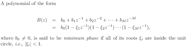
As usual, definitions for filters generalize to definitions for signals by simply treating the signal as an impulse response:
Note that every stable all-pole filter
![]() is
minimum phase, because stability implies that
is
minimum phase, because stability implies that ![]() is minimum
phase, and there are ``no zeros'' (all are at
is minimum
phase, and there are ``no zeros'' (all are at ![]() ).
Thus, minimum phase is the only phase available to a stable all-pole
filter.
).
Thus, minimum phase is the only phase available to a stable all-pole
filter.
The contribution of minimum-phase zeros to the complex cepstrum was described in §8.8.
Maximum Phase Filters
The opposite of minimum phase is maximum phase:
For example, every stable allpass filter (§B.2) is a maximum-phase filter, because its transfer function can be written as
If zeros of ![]() occur both inside and outside the unit circle, the
filter is said to be a mixed-phase filter. Note that zeros on
the unit circle are neither minimum nor maximum phase according to our
definitions. Since poles on the unit circle are sometimes called
``marginally stable,'' we could say that zeros on the unit circle are
``marginally minimum and/or maximum phase'' for consistency. However,
such a term does not appear to be very useful. When pursuing
minimum-phase filter design (see §11.7), we will
find that zeros on the unit circle must be treated separately.
occur both inside and outside the unit circle, the
filter is said to be a mixed-phase filter. Note that zeros on
the unit circle are neither minimum nor maximum phase according to our
definitions. Since poles on the unit circle are sometimes called
``marginally stable,'' we could say that zeros on the unit circle are
``marginally minimum and/or maximum phase'' for consistency. However,
such a term does not appear to be very useful. When pursuing
minimum-phase filter design (see §11.7), we will
find that zeros on the unit circle must be treated separately.
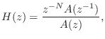
If ![]() is order
is order ![]() and minimum phase, then
and minimum phase, then
![]() is
maximum phase, and vice versa. To restate this in the time domain, if
is
maximum phase, and vice versa. To restate this in the time domain, if
![]() is a minimum-phase FIR sequence of
length
is a minimum-phase FIR sequence of
length ![]() , then
SHIFT
, then
SHIFT![]() FLIP
FLIP![]() is a maximum-phase sequence.
In other words, time reversal inverts the locations of all
zeros, thereby ``reflecting'' them across the unit circle in a manner
that does not affect spectral magnitude. Time reversal is followed by
a shift in order to obtain a causal result, but this is not required:
Adding a pure delay to a maximum-phase filter (
is a maximum-phase sequence.
In other words, time reversal inverts the locations of all
zeros, thereby ``reflecting'' them across the unit circle in a manner
that does not affect spectral magnitude. Time reversal is followed by
a shift in order to obtain a causal result, but this is not required:
Adding a pure delay to a maximum-phase filter (
![]() ) gives a new maximum-phase filter with the same amplitude
response (and order increased by 1).
) gives a new maximum-phase filter with the same amplitude
response (and order increased by 1).
Example
It is easy to classify completely all first-order FIR filters:
Minimum Phase Means Fastest Decay
The previous example is an instance of the following general result:
That is, the signal energy in the first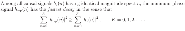
Minimum-Phase/Allpass Decomposition
Every causal stable filter ![]() with no zeros on the unit
circle can be factored into a minimum-phase filter in cascade with a
causal stable allpass filter:
with no zeros on the unit
circle can be factored into a minimum-phase filter in cascade with a
causal stable allpass filter:
This result is easy to show by induction. Consider a single
maximum-phase zero ![]() of
of ![]() . Then
. Then
![]() , and
, and ![]() can be written with the maximum-phase zero factored out as
can be written with the maximum-phase zero factored out as
In summary, we may factor maximum-phase zeros out of the transfer function and replace them with their minimum-phase counterparts without altering the amplitude response. This modification is equivalent to placing a stable allpass filter in series with the original filter, where the allpass filter cancels the maximum-phase zero and introduces the minimum-phase zero.
A procedure for computing the minimum phase for a given spectral magnitude is discussed in §11.7 below. More theory pertaining to minimum phase sequences may be found in [60].
Is Linear Phase Really Ideal for Audio?
It is generally accepted that zero or linear phase filters are ideal for audio applications. This is because such filters delay all frequencies by the same amount, thereby maximally preserving waveshape. Mathematically, all Fourier-components passed by the filter remain time-synchronized exactly as they were in the original signal. However, this section will argue that a phase response somewhere between linear- and minimum-phase may be even better in some cases. We show this by means of a Matlab experiment comparing minimum-phase and zero-phase impulse responses.
The matlab code is shown in Fig.11.1. An order ![]() elliptic-function lowpass filter [64] is designed
with a cut-off frequency at 2 kHz. We choose an elliptic-function
filter because it has a highly nonlinear phase response near its
cut-off frequency, resulting in extra delay there which can be
perceived as ``ringing'' at that frequency. The cut-off is chosen at
2kHz because this is a highly audible frequency. We want to clearly
hear the ringing in this experiment in order to compare the zero-phase
and minimum-phase cases.
elliptic-function lowpass filter [64] is designed
with a cut-off frequency at 2 kHz. We choose an elliptic-function
filter because it has a highly nonlinear phase response near its
cut-off frequency, resulting in extra delay there which can be
perceived as ``ringing'' at that frequency. The cut-off is chosen at
2kHz because this is a highly audible frequency. We want to clearly
hear the ringing in this experiment in order to compare the zero-phase
and minimum-phase cases.
% ellipt.m - Compare minimum-phase and zero-phase % lowpass impulse responses. dosounds = 1; N = 8; % filter order Rp = 0.5; % passband ripple (dB) Rs = 60; % stopband ripple (-dB) Fs = 8192; % default sampling rate (Windows Matlab) Fp = 2000; % passband end Fc = 2200; % stopband begins [gives order 8] Ns = 4096; % number of samples in impulse responses [B,A] = nellip(Rp, Rs, Fp/(0.5*Fs), Fc/(0.5*Fs)); % Octave % [B,A] = ellip(N, Rp, Rs, Fp/(0.5*Fs)); % Matlab % Minimum phase case: imp = [1,zeros(1,Ns/2-1)]; % or 'h1=impz(B,A,Ns/2-1)' h1 = filter(B,A,imp); % min-phase impulse response hmp = filter(B,A,[h1,zeros(1,Ns/2)]); % apply twice % Zero phase case: h1r = fliplr(h1); % maximum-phase impulse response hzp = filter(B,A,[h1r,zeros(1,Ns/2)]); % min*max=zp % hzp = fliplr(hzp); % not needed here since symmetric elliptplots; % plot impulse- and amplitude-responses % Let's hear them! while(dosounds) sound(hmp,Fs); pause(0.5); sound(hzp,Fs); pause(1); end |
Let the impulse response of the ![]() th order lowpass filter be denoted
th order lowpass filter be denoted
![]() . It is neither minimum nor maximum phase because there are
zeros on the unit circle. (An elliptic-function filter has all of its
zeros on the unit circle.) However, nothing of practical
importance changes if we move the zeros from radius 1 to radius
. It is neither minimum nor maximum phase because there are
zeros on the unit circle. (An elliptic-function filter has all of its
zeros on the unit circle.) However, nothing of practical
importance changes if we move the zeros from radius 1 to radius
![]() , say, which would give a minimum-phase perturbation of
the elliptic lowpass.
, say, which would give a minimum-phase perturbation of
the elliptic lowpass.
From ![]() we prepare two impulse responses having the same
magnitude spectra but different phase spectra:
we prepare two impulse responses having the same
magnitude spectra but different phase spectra:
again as discussed in §10.6.
Since we are listening to a lowpass-filtered impulse, it is reasonable
to define the ideal expected sound as a ``lowpass-filtered click,'' or
some kind of ``compact thump.'' We may therefore ask which signal
sounds more like a lowpassed click,
![]() or
or
![]() ? In the
minimum-phase case, all filter ringing occurs after the main pulse,
while in the zero-phase case, it is equally divided before and after
the main pulse (see Fig.11.2). Listening tests confirm that the
``pre-ring'' of the zero-phase case is audible before the main click,
giving it a kind of ``chirp'' quality. Most listeners would say the
minimum-phase case is a better ``click''. Since forward masking is
stronger than backward masking in hearing perception, the optimal
distribution of ringing is arguably a small amount before the main
pulse (however much is inaudible due to backward masking, for
example), with the rest occurring after the main pulse.
? In the
minimum-phase case, all filter ringing occurs after the main pulse,
while in the zero-phase case, it is equally divided before and after
the main pulse (see Fig.11.2). Listening tests confirm that the
``pre-ring'' of the zero-phase case is audible before the main click,
giving it a kind of ``chirp'' quality. Most listeners would say the
minimum-phase case is a better ``click''. Since forward masking is
stronger than backward masking in hearing perception, the optimal
distribution of ringing is arguably a small amount before the main
pulse (however much is inaudible due to backward masking, for
example), with the rest occurring after the main pulse.
![\includegraphics[width=\twidth]{eps/elliptt}](http://www.dsprelated.com/josimages_new/filters/img1286.png) |
Figure 11.3 verifies that the magnitude spectra are the same in each case.
![\includegraphics[width=\twidth]{eps/elliptf}](http://www.dsprelated.com/josimages_new/filters/img1287.png) |
Creating Minimum Phase Filters
and Signals
Minimum-phase filter design often requires creating a minimum-phase
desired frequency response
![]() from a given magnitude response
from a given magnitude response
![]() ). As is clear from
§11.5, any filter transfer function
). As is clear from
§11.5, any filter transfer function ![]() can be made
minimum-phase, in principle, by completely factoring
can be made
minimum-phase, in principle, by completely factoring ![]() and
``reflecting'' all zeros
and
``reflecting'' all zeros ![]() for which
for which ![]() inside the
unit circle, i.e., replacing
inside the
unit circle, i.e., replacing ![]() by
by ![]() . However, factoring a
polynomial this large can be impractical. An approximate
``nonparametric'' method12.3is based on the property of the complex cepstrum
(see §8.8) that each minimum-phase zero in the spectrum
gives rise to a causal exponential in the cepstrum, while each
maximum-phase zero corresponds to an anti-causal exponential in the
cepstrum [60]. Therefore, by computing the
cepstrum and converting anti-causal exponentials to causal
exponentials, the corresponding spectrum is
converted nonparametrically to minimum-phase form.
. However, factoring a
polynomial this large can be impractical. An approximate
``nonparametric'' method12.3is based on the property of the complex cepstrum
(see §8.8) that each minimum-phase zero in the spectrum
gives rise to a causal exponential in the cepstrum, while each
maximum-phase zero corresponds to an anti-causal exponential in the
cepstrum [60]. Therefore, by computing the
cepstrum and converting anti-causal exponentials to causal
exponentials, the corresponding spectrum is
converted nonparametrically to minimum-phase form.
A matlab function mps.m which carries out this method is listed in §J.11.12.4It works best for smooth desired frequency response curves, but in principle the error can be made arbitrarily small by simply enlarging the FFT sizes used. Specifically, the inverse FFT of the log magnitude frequency response should not ``wrap around'' in the time domain (negligible ``time aliasing'').
It is important to use something like mps when designing digital filters based on a magnitude frequency-response specification using ``phase sensitive'' filter-design software (such as invfreqz in matlab). In other words, poor results are generally obtained when phase-sensitive filter-design software is asked to design a causal, stable, zero-phase filter. As a general rule, when phase doesn't matter, ask for minimum phase.
A related practical note is that unstable recursive filter designs can often be stabilized by simply adding more delay to the desired impulse response (i.e., adding a negatively sloped linear phase to the desired phase response). For example, the Steiglitz-McBride algorithm in Matlab (stmcb) is a phase-sensitive IIR filter-design function that accepts a desired impulse response, while Matlab's invfreqz (which can optionally iterate toward the Steiglitz-McBride solution), accepts a complex desired frequency response.
Next Section:
Conclusion
Previous Section:
Filters Preserving Phase


