


Allpass Filters
This appendix addresses the general problem of characterizing all digital allpass filters, including multi-input, multi-output (MIMO) allpass filters. As a result of including the MIMO case, the mathematical level is a little higher than usual for this book. The reader in need of more background is referred to [84,37,98].Our first task is to show that losslessness implies allpass.
Definition:
A linear, time-invariant filter ![]() is said to be
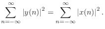
lossless if it preserves signal
energy for every input signal. That is, if the input signal is
is said to be
lossless if it preserves signal
energy for every input signal. That is, if the input signal is
![]() , and the output signal is
, and the output signal is
![]() , then we have
, then we have
Notice that only stable filters can be lossless, since otherwise
![]() can be infinite while
can be infinite while
![]() is finite. We further
assume all filters are causalC.1 for
simplicity. It is straightforward to show the following:
is finite. We further
assume all filters are causalC.1 for
simplicity. It is straightforward to show the following:
Theorem: A stable, linear, time-invariant (LTI) filter transfer function
![]() is lossless if and only if
is lossless if and only if
Proof: We allow the signals ![]() and filter impulse response
and filter impulse response
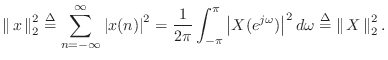
![]() to be complex. By Parseval's theorem
[84] for the DTFT, we have,C.2 for any signal
to be complex. By Parseval's theorem
[84] for the DTFT, we have,C.2 for any signal
![]() ,
,
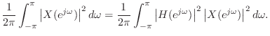
Since this must hold for all
We have shown that every lossless filter is allpass. Conversely, every unity-gain allpass filter is lossless.
Allpass Examples
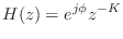
- The simplest allpass filter is a unit-modulus gain
where

 can be any phase value. In the real case
can only be 0 or
can be any phase value. In the real case
can only be 0 or  , in which case
 .
.
- A lossless FIR filter can consist only of a single nonzero tap:
for some fixed integer
 , where is again some constant phase,
constrained to be 0 or in the real-filter case. Since we are
considering only causal filters here,
, where is again some constant phase,
constrained to be 0 or in the real-filter case. Since we are
considering only causal filters here,  . As a special case of
this example, a unit delay
. As a special case of
this example, a unit delay
 is a simple FIR allpass filter.
- The transfer function of every finite-order, causal,
lossless IIR digital filter (recursive allpass filter) can be written
as
where
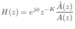 ,
and
,
and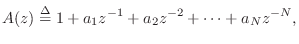
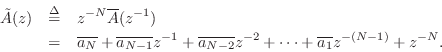
We may think of
 as the flip of
  . For example,
if
. For example,
if
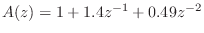 , we have
 . Thus,
is obtained from by simply reversing the order of the
coefficients and conjugating them when they are complex.
. Thus,
is obtained from by simply reversing the order of the
coefficients and conjugating them when they are complex.
- For analog filters, the general finite-order allpass
transfer function is
where
 ,
,
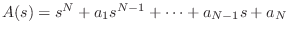 .
The polynomial
.
The polynomial  can be obtained by negating every other
coefficient in , and multiplying by
can be obtained by negating every other
coefficient in , and multiplying by  . In analog, a pure
delay of
. In analog, a pure
delay of  seconds corresponds to the transfer function
which is infinite order. Given a pole
seconds corresponds to the transfer function
which is infinite order. Given a pole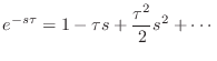
 (root of
  at
at  ),
the polynomial has a root at
),
the polynomial has a root at  . Thus, the poles and
zeros can be paired off as a cascade of terms such as
The frequency response of such a term is
. Thus, the poles and
zeros can be paired off as a cascade of terms such as
The frequency response of such a term is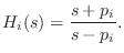 which is obviously unit magnitude.
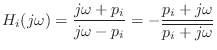
Paraunitary FiltersC.4
Another way to express the allpass condition
![]() is to
write
is to
write
Definition: The
paraconjugate of a transfer function may be defined as the
analytic continuation of the complex conjugate from the unit circle to
the whole ![]() plane:
plane:
Examples:
We refrain from conjugating ![]() in the definition of the paraconjugate
because
in the definition of the paraconjugate
because
![]() is not analytic in the complex-variables sense.
Instead, we invert
is not analytic in the complex-variables sense.
Instead, we invert ![]() , which is analytic, and which
reduces to complex conjugation on the unit circle.
, which is analytic, and which
reduces to complex conjugation on the unit circle.
The paraconjugate may be used to characterize allpass filters as follows:
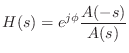
Theorem: A causal, stable, filter ![]() is allpass if and only if
is allpass if and only if
Multi-Input, Multi-Output (MIMO)
Allpass Filters
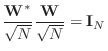
To generalize lossless filters to the multi-input, multi-output (MIMO) case, we must generalize conjugation to MIMO transfer function matrices:
Theorem: A ![]() transfer function matrix
transfer function matrix
![]() is
lossless if and only if
its frequency-response matrix
is
lossless if and only if
its frequency-response matrix
![]() is unitary, i.e.,
is unitary, i.e.,
for all
Let
![]() denote the length
denote the length ![]() output vector at time
output vector at time ![]() , and
let
, and
let
![]() denote the input
denote the input ![]() -vector at time
-vector at time ![]() . Then in the
frequency domain we have
. Then in the
frequency domain we have
![]() , which
implies
, which
implies
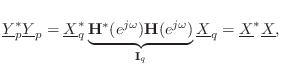
We have thus shown that in the MIMO case, losslessness is equivalent to having a unitary frequency-response matrix. A MIMO allpass filter is therefore any filter with a unitary frequency-response matrix.
Note that
![]() is a
is a ![]() matrix product
of a
matrix product
of a ![]() times a
times a ![]() matrix. If
matrix. If ![]() , then the rank
must be deficient. Therefore,
, then the rank
must be deficient. Therefore, ![]() . (There must be at least as
many outputs as there are inputs, but it's ok to have extra outputs.)
. (There must be at least as
many outputs as there are inputs, but it's ok to have extra outputs.)
Paraunitary MIMO Filters
In §C.2, we generalized the allpass property
![]() to the entire complex plane as
to the entire complex plane as
MIMO Paraconjugate
Definition:
The paraconjugate of
![]() is defined as
is defined as
![$\displaystyle \mathbf{H}(z)=\left[\begin{array}{c} 1+jz^{-1} \\ [2pt] 1+z^{-2} \end{array}\right]
$](http://www.dsprelated.com/josimages_new/filters/img1628.png)
MIMO Paraunitary Condition
With the above definition for paraconjugation of a MIMO transfer-function
matrix, we may generalize the MIMO allpass condition Eq.![]() (C.2) to the
entire
(C.2) to the
entire ![]() plane as follows:
plane as follows:
Theorem:
Every lossless ![]() transfer function matrix
transfer function matrix
![]() is paraunitary,
i.e.,
is paraunitary,
i.e.,
By construction, every paraunitary matrix transfer function is
unitary on the unit circle for all ![]() . Away from the
unit circle, the paraconjugate
. Away from the
unit circle, the paraconjugate
![]() is the unique analytic
continuation of
is the unique analytic
continuation of
![]() (the Hermitian transpose of
(the Hermitian transpose of
![]() ).
).
Example:
The normalized DFT matrix is an ![]() order zero
paraunitary transformation. This is because the normalized DFT
matrix,
order zero
paraunitary transformation. This is because the normalized DFT
matrix,
![]() , where
, where
![]() , is a
unitary matrix:
, is a
unitary matrix:
Properties of Paraunitary Systems
Paraunitary systems are essentially multi-input, multi-output (MIMO)
allpass filters. Let
![]() denote the
denote the ![]() matrix transfer
function of a paraunitary system. Some of its properties include the
following [98]:
matrix transfer
function of a paraunitary system. Some of its properties include the
following [98]:
- In the square case (
 ), the matrix determinant,
![$ \det[\mathbf{H}(z)]$](http://www.dsprelated.com/josimages_new/filters/img1637.png) , is an allpass filter.
, is an allpass filter.
- Therefore, if a square
 contains FIR elements, its
determinant is a simple delay:
contains FIR elements, its
determinant is a simple delay:
![$ \det[\mathbf{H}(z)]=z^{-K}$](http://www.dsprelated.com/josimages_new/filters/img1638.png) for some
integer .
for some
integer .
Properties of Paraunitary Filter Banks
An ![]() -channel filter bank can be viewed as an
-channel filter bank can be viewed as an ![]() MIMO filter
MIMO filter
![$\displaystyle \mathbf{H}(z) = \left[\begin{array}{c} H_1(z) \\ [2pt] H_2(z) \\ [2pt] \vdots \\ [2pt] H_N(z)\end{array}\right]
$](http://www.dsprelated.com/josimages_new/filters/img1640.png)
A paraunitary filter bank must therefore obey
We can note the following properties of paraunitary filter banks:
- A synthesis filter bank
 corresponding
to analysis filter bank
is defined as that filter bank
which inverts the analysis filter bank, i.e., satisfies
Clearly, not every filter bank will be invertible in this way. When it is, it may be called a perfect reconstruction filter bank. When a filter bank transfer function
corresponding
to analysis filter bank
is defined as that filter bank
which inverts the analysis filter bank, i.e., satisfies
Clearly, not every filter bank will be invertible in this way. When it is, it may be called a perfect reconstruction filter bank. When a filter bank transfer function is paraunitary, its
corresponding synthesis filter bank is simply the paraconjugate filter
bank
is paraunitary, its
corresponding synthesis filter bank is simply the paraconjugate filter
bank
 , or
, or

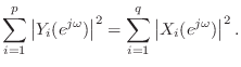
- The channel filters
 in a paraunitary filter bank
are power complementary:
This follows immediately from looking at the paraunitary property on the unit circle.
in a paraunitary filter bank
are power complementary:
This follows immediately from looking at the paraunitary property on the unit circle.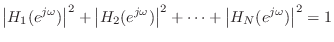
- When
is FIR, the corresponding synthesis filter
matrix
is also FIR. Note that this implies an FIR
filter-matrix can be inverted by another FIR filter-matrix. This is in
stark contrast to the case of single-input, single-output FIR filters,
which must be inverted by IIR filters, in general.
- When
is FIR, each synthesis filter,
 , is simply the
  of its corresponding
analysis filter
of its corresponding
analysis filter
 :
where
:
where
 is the filter length. (When the filter coefficients are
complex, includes a complex conjugation as well.)
is the filter length. (When the filter coefficients are
complex, includes a complex conjugation as well.)
This follows from the fact that paraconjugating an FIR filter amounts to simply flipping (and conjugating) its coefficients.
Note that only trivial FIR filters can be paraunitary in the single-input, single-output (SISO) case. In the MIMO case, on the other hand, paraunitary systems can be composed of FIR filters of any order.
- FIR analysis and synthesis filters in paraunitary filter banks
have the same amplitude response.
This follows from the fact that
 , i.e., flipping an FIR filter impulse response
  conjugates the frequency response, which does not affect its amplitude
response
conjugates the frequency response, which does not affect its amplitude
response
 .
.
Paraunitary Filter Examples
The Haar filter bank is defined as
![$\displaystyle \mathbf{H}(z) = \frac{1}{\sqrt{2}}\left[\begin{array}{c} 1+z^{-1} \\ [2pt] 1-z^{-1} \end{array}\right]
$](http://www.dsprelated.com/josimages_new/filters/img1655.png)
![$\displaystyle {\tilde{\mathbf{H}}}(z) \mathbf{H}(z) = \left[\begin{array}{cc} 1...
...ight] \left[\begin{array}{c} 1+z^{-1} \\ [2pt] 1-z^{-1} \end{array}\right]
= 1
$](http://www.dsprelated.com/josimages_new/filters/img1657.png)
For more about paraunitary filter banks, see Chapter 6 of [98].
Allpass Problems
- The BiQuad Allpass Section
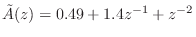
- Show that every second-order filter having transfer function
is a unit-gain allpass filter. That is, show that
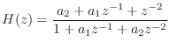
 ,
for all
,
for all  and
and  . (Typically, and are chosen such
that the filter is stable, but this is not necessary for the result to hold.)
. (Typically, and are chosen such
that the filter is stable, but this is not necessary for the result to hold.)
- Find the zeros of the filter as a function of the poles.
In other words, given two poles, what is the rule for placing the zeros
in order to obtain an allpass filter?
- Find the phase response of the zeros in terms of the phase response of the poles.
- Show that every second-order filter having transfer function
Next Section:
Introduction to Laplace Transform Analysis
Previous Section:
Elementary Audio Digital Filters


