


Delay-Line Damping Filter Design
Let
![]() denote the desired reverberation time at radian frequency
denote the desired reverberation time at radian frequency
![]() , and let
, and let ![]() denote the transfer function of the lowpass
filter to be placed in series with the
denote the transfer function of the lowpass
filter to be placed in series with the ![]() th delay line which is
th delay line which is ![]() samples long. The problem we consider now is how to design these
filters to yield the desired reverberation time. We will specify an
ideal amplitude response for
samples long. The problem we consider now is how to design these
filters to yield the desired reverberation time. We will specify an
ideal amplitude response for ![]() based on the desired
reverberation time at each frequency, and then use conventional
filter-design methods to obtain a low-order approximation to this
ideal specification.
based on the desired
reverberation time at each frequency, and then use conventional
filter-design methods to obtain a low-order approximation to this
ideal specification.
In accordance with Eq.![]() (3.6), the lowpass filter
(3.6), the lowpass filter ![]() in series
with a length
in series
with a length ![]() delay line should approximate
delay line should approximate
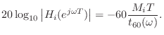
This is the same formula derived by Jot [217] using a somewhat different approach.
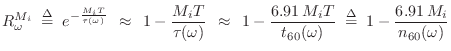
Now that we have specified the ideal delay-line filter
![]() in
terms of its amplitude response in dB, any number of filter-design
methods can be used to find a low-order
in
terms of its amplitude response in dB, any number of filter-design
methods can be used to find a low-order ![]() which provides a good
approximation to satisfying Eq.
which provides a good
approximation to satisfying Eq.![]() (3.9). Examples include the functions
invfreqz and stmcb in Matlab. Since the variation
in reverberation time is typically very smooth with respect to
(3.9). Examples include the functions
invfreqz and stmcb in Matlab. Since the variation
in reverberation time is typically very smooth with respect to
![]() , the filters
, the filters ![]() can be very low order.
can be very low order.
First-Order Delay-Filter Design
The first-order case is very simple while enabling separate control of
low-frequency and high-frequency reverberation times. For simplicity,
let's specify ![]() and
and
![]() , denoting the desired
decay-time at dc (
, denoting the desired
decay-time at dc (![]() ) and half the sampling rate
(
) and half the sampling rate
(
![]() ). Then we have determined the coefficients of a
one-pole filter:
). Then we have determined the coefficients of a
one-pole filter:
![\begin{eqnarray*}
\frac{g_i}{1-p_i} &=& 10^{-3 M_i T / t_{60}(0)}
\eqsp e^{-M_iT...
...(\pi/T)}
\eqsp e^{-M_iT/\tau(\pi/T)} \isdefs R_\pi^{M_i}\\ [5pt]
\end{eqnarray*}](http://www.dsprelated.com/josimages_new/pasp/img870.png)
where
![]() denotes the
denotes the ![]() th delay-line length in
seconds. These two equations are readily solved to yield
th delay-line length in
seconds. These two equations are readily solved to yield
![\begin{eqnarray*}
p_i &=& \frac{R_0^{M_i}-R_\pi^{M_i}}{R_0^{M_i}+R_\pi^{M_i}}\\ [5pt]
g_i &=& \frac{2R_0^{M_i}R_\pi^{M_i}}{R_0^{M_i}+R_\pi^{M_i}}
\end{eqnarray*}](http://www.dsprelated.com/josimages_new/pasp/img872.png)
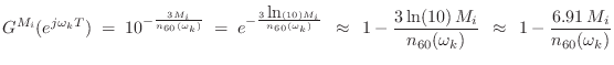
The truncated series approximation
Orthogonalized First-Order Delay-Filter Design
In [217], first-order delay-line filters of the form

denotes the ratio of reverberation time at half the sampling rate divided by the reverberation time at dc.4.16
Multiband Delay-Filter Design
In §3.7.5, we derived first-order FDN delay-line filters which
can independently set the reverberation time at dc and at half the
sampling rate. However, perceptual studies indicate that
reverberation time should be independently adjustable in at least
three frequency bands [217]. To provide this degree
of control (and more), one can implement a multiband delay-line filter
using a general-purpose filter bank
[370,500]. The output, say, of each delay
line is split into ![]() bands, where
bands, where ![]() is recommended, and then,
from Eq.
is recommended, and then,
from Eq.![]() (3.6), the gain in the
(3.6), the gain in the ![]() th band for a length
th band for a length ![]() delay-line can be set to
delay-line can be set to
Next Section:
Spectral Coloration Equalizer
Previous Section:
Achieving Desired Reverberation Times


