


Rick Lyons posted an informative post about testing the implementation of your #CIC decimation filters here: Two Easy Ways to Test Multistage CIC Decimation Filters I have been working on implementing such a filter and found the article informative but it has added more confusion than light at the moment. I realized I've got some assumptions about how these things work that may be incorrect so I'm posting this check in here.
I have assumed that a cascade of integrators takes the output of one integrator and feeds into the next integrator. I have further assumed that at the point where you decimate, the value being held by the last integrator in the cascade is the X(n) input into the first comb. Further I assume that the output of each comb become the X(n) input of the next comb, (for M = 2, it would be the comb prior to the previous comb).
That said, Rick's paper gives the first 10 output values (in test 1) for a 3 stage CIC decimation filter that is fed a unity pulse followed by zeros. The decimation factor is stated as 5 and while M isn't stated, the diagram suggests it is '1'. His test generates, three non-zero values, 1, 18, and 6. followed by zeros. Mine generates and ever ascending value: 1, 18, 9, 54, 24, 108, 46, ...
To understand that, I wrote some code to implement this 3 stage CIC and printed the state of each integrator and each comb to understand what it was doing. These are the first 10 cycles (at the 'high' frequency, which after being decimated by 5 generate the first five outputs (1, 18, 9, 54, and 24)
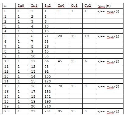
For D = 5, 10 output samples:
 Cycle :  Xn : In0 : In1 : In2 :  Co0 :  Co1 :  Co2 : Y[n]
-------+-----+-----+-----+-----+----- +------+------+------
*    0 :   1 :   1 :   1 :   1 :    1 :    1 :    1 : y[0]
     1 :   0 :   1 :   2 :   3 :      :      :      :
     2 :   0 :   1 :   3 :   6 :      :      :      :
     3 :   0 :   1 :   4 :  10 :      :      :      :
     4 :   0 :   1 :   5 :  15 :      :      :      :
*    5 :   0 :   1 :   6 :  21 :   20 :   19 :   18 : y[1]
     6 :   0 :   1 :   7 :  28 :      :      :      :
     7 :   0 :   1 :   8 :  36 :      :      :      :
     8 :   0 :   1 :   9 :  45 :      :      :      :
     9 :   0 :   1 :  10 :  55 :      :      :      :
*   10 :   0 :   1 :  11 :  66 :   46 :   27 :    9 : y[2]
    11 :   0 :   1 :  12 :  78 :      :      :      :
    12 :   0 :   1 :  13 :  91 :      :      :      :
    13 :   0 :   1 :  14 : 105 :      :      :      :
    14 :   0 :   1 :  15 : 120 :      :      :      :
*   15 :   0 :   1 :  16 : 136 :   90 :   63 :   54 : y[3]
    16 :   0 :   1 :  17 : 153 :      :      :      :
    17 :   0 :   1 :  18 : 171 :      :      :      :
    18 :   0 :   1 :  19 : 190 :      :      :      :
    19 :   0 :   1 :  20 : 210 :      :      :      :
*   20 :   0 :   1 :  21 : 231 :  141 :   78 :   24 : y[4]
    21 :   0 :   1 :  22 : 253 :      :      :      :
    22 :   0 :   1 :  23 : 276 :      :      :      :
    23 :   0 :   1 :  24 : 300 :      :      :      :
    24 :   0 :   1 :  25 : 325 :      :      :      :
*   25 :   0 :   1 :  26 : 351 :  210 :  132 :  108 : y[5]
The column headers indicate the state of the Integrators (In0 .. In2) and Combs (Co0 ... Co2), with Xn on the left being the input sample and Yn on the right being the output sample.
You can see that during the first 5 cycles, the first integrator sees 1, 0, 0, 0, 0. The second integrator sees 1, 1, 1, 1, 1, 1. The third integrator sees 0, 1, 2, 3, 4, 5. On the 5th cycle, the third integrator is holding 21 and that is the value that the first comb sees.
The Comb's state is the previous value that it saw. At the start (cycle 0) which is nominally a decimation output since cycle mod D is zero, the combs fill up with the value 1. At cycle 5, comb 0 has 1, see's 21 to its left, and so outputs 21 - 1 or 20. Comb 1 was also holding 1, sees 20 to its left, so it outputs 20 - 1 or 19, comb 3 was holding 1, sees 18 to its left its state becomes 19 - 1 or 18.
In my code, Y[n] is the computes value in Comb 2 (the third comb). Cycle 0 generates a 1, cycle 1 generates 18, and cycle 2 generates 9. The value 9 differs from Rick's test, and certainly the next value (54 differs a lot from 0). The output never goes to 0 per Rick's comments on the output from this test.
So two concrete questions I'm working on;
- Why is the third output 9 rather than 6?
- Why doesn't my CIC filter code's output generate a 'sequence of zeros'?

Below is my listing of the integrators/differentiators outputs for a 3-stage decimate-by-5 CIC decimator.
The impulse response output of the 3rd differentiator (above column Co2) should be finite in duration. (That is, only a finite number of non-zero-valued impulse response samples.) It seems to me that you may not be implementing your differentiators (comb filters) properly. Please let me know what you think about my above listing.

Hi Rick,
There is certainly something different in the differentiators :-).
From your first response I use M = 1, so the differentiator is looking at X(n) and Y(n - 1). That appears to be the case for you as well. If you don't mind, I'm going to introduce a notation [cyc,fn] which is the value of a function (top row after 'n') on a given cycle (shown as number in column one).
The differentiators X(n) comes from the column to their left, and the value of X(n - 1) is the last value the differentiator produced so it is from [CoN,n-5] (where N is 0, 1, or 2). Looking at row 5 for example:
Co0 takes X(n) from the left (21), and the previous value [5,Co0] = 1 as X(n-1) which is (1). Subtracts them (21 - 1) and stores 20 as its output. Co1, and Co2 work similarly.
But on cycle 10 things are different. For Co0, the input is 66 [10,In2], the previous value is 20 [5,Co0], 66 - 20 is 46, not 45 as your box has it. Similarly Co1 has X(n) value 45 (now off by one) [10, Co0], and previous value of 19 [5, Co1]. 45 - 19 is 26, but your value is 25, off by another value of 1. And the final differentiator X(n) is 25, X(n-1) is 18, so 25-18 would be 7.
So an interesting question is where is the factor '1' coming from that your differentiators are removing on line 10.
The answer reveals itself with line 15. The only way to get the differentiator values that you get is to have each differentiator subtract every value it has ever seen from the next input.
What this means that the differentiator in your matlab code is implemented as
$$Y(n) = X(n) - \sum_{i=0}^{i=n-1}(Y(n-i))$$
That was not my understanding of the how the differentiator worked.
If I understand your latest Comment that begins with "There is certainly something...", it seems to me you are implementing your first comb filter (Co0) as shown in the following diagram:
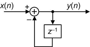
which is not correct. Instead, all three comb filters should be implemented as shown in the following diagram:
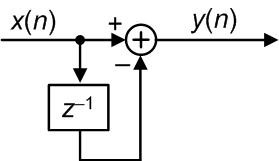
The first five input samples applied to your first comb filter are [1,21,66,136,231]. If you apply those five samples to a comb filter the filter's output sequence should be [1,20,45,70,95].
Hi Rick,
[Side note: the pictures are awesome!]
Your understanding is correct. Having the two pictures is also pretty cool since its easier to see how diagrammatically they are different.
What I've been missing appears to be that the arrow "into" \(z^{-1}\) is a summing operator not a replacement operator. I have been interpreting that diagram to mean "a copy of the stream of x(n), using the sample previous to the current sample (the -1), feed that into the summing operation after inverting its sign (turning it into a subtraction), and that becomes the output."
Now in the integrator case the code is that \(y[n] = y[n-1] + x[n]\) there the sum of the previous output and the new input become the new output. That was pretty clear.
For the comb the code is \(y[n] = x[n] - x[n-M]\). Because both terms are 'x' terms, I was not feeding back the output into the input. That leaves me at a loss though for implementing values of M other than 1. Do they sum every other output? Some more research and off to read Hoganauer again.
I'm pleased that I have code that can duplicate your output. Now if I can get a true understanding of why it is that way, then I can declare victory and move on to IIR filters or start debugging my polyphase filter. (saving that one for last)
Hi ChuckMcM.
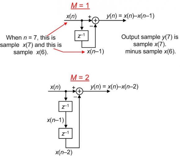
Regarding the 2nd paragraph of your latest Comment that begins with "[Side note:...", the "arrow into z−1 block combined with the z-1 block" are not a summing operator, but rather that combination is a "shifting" operation. It means: after computing a y(n) output sample, shift (or "move") the contents of the memory location containing the x(n) sample to the memory location containing the x(n-1) sample in preparation for the arrival of the x(n+1) sample.
Regarding the 4th paragraph of your Comment, there is no feedback in a comb filter. See the following comb filter diagrams:
Rick,
Thank you so much for your patience. You have helped connect a number of dots for me (that explanation of the diagram is brilliant).
For other readers of this thread, fundamentally the error in my combs (looking at my table) was that my combs were using their own previous output as the \(X[n-1]\) term. That is (now) clearly incorrect. So I updated my code to store both the \(Y[n]\) output, and the \(X[n]\) input, after the computation is done with the value of \(X[n]\) stored from the previous computation. (this implements the 'shift' that Rick describes above.)
For grins I have included the updated output below. The thing to notice here is that now the combs work as numerical differentiators as I expected them to (see my response to gretzteam below). The first comb changes the quadratic growth of the last integrator into linear growth, the second comb changes the linear growth of the previous comb into a constant, and the output of the final comb is zero (differentiating a constant) when the input is constant (in this case 0).
For D = 5, 10 output samples:
 Cycle :  Xn : In0 : In1 : In2 :  Co0 :  Co1 :  Co2 : Y[n]
-------+-----+-----+-----+-----+----- +------+------+------
*    0 :   1 :   1 :   1 :   1 :    1 :    1 :    1 : y[0]
     1 :   0 :   1 :   2 :   3 :      :      :      :
     2 :   0 :   1 :   3 :   6 :      :      :      :
     3 :   0 :   1 :   4 :  10 :      :      :      :
     4 :   0 :   1 :   5 :  15 :      :      :      :
*    5 :  19 :   1 :   6 :  21 :   20 :   19 :   18 : y[1]
     6 :   0 :   1 :   7 :  28 :      :      :      :
     7 :   0 :   1 :   8 :  36 :      :      :      :
     8 :   0 :   1 :   9 :  45 :      :      :      :
     9 :   0 :   1 :  10 :  55 :      :      :      :
*   10 :  25 :   1 :  11 :  66 :   45 :   25 :    6 : y[2]
    11 :   0 :   1 :  12 :  78 :      :      :      :
    12 :   0 :   1 :  13 :  91 :      :      :      :
    13 :   0 :   1 :  14 : 105 :      :      :      :
    14 :   0 :   1 :  15 : 120 :      :      :      :
*   15 :  25 :   1 :  16 : 136 :   70 :   25 :    0 : y[3]
    16 :   0 :   1 :  17 : 153 :      :      :      :
    17 :   0 :   1 :  18 : 171 :      :      :      :
    18 :   0 :   1 :  19 : 190 :      :      :      :
    19 :   0 :   1 :  20 : 210 :      :      :      :
*   20 :  25 :   1 :  21 : 231 :   95 :   25 :    0 : y[4]
    21 :   0 :   1 :  22 : 253 :      :      :      :
    22 :   0 :   1 :  23 : 276 :      :      :      :
    23 :   0 :   1 :  24 : 300 :      :      :      :
    24 :   0 :   1 :  25 : 325 :      :      :      :
*   25 :  25 :   1 :  26 : 351 :  120 :   25 :    0 : y[5]
    26 :   0 :   1 :  27 : 378 :      :      :      :
    27 :   0 :   1 :  28 : 406 :      :      :      :
    28 :   0 :   1 :  29 : 435 :      :      :      :
    29 :   0 :   1 :  30 : 465 :      :      :      :
*   30 :  25 :   1 :  31 : 496 :  145 :   25 :    0 : y[6]
    31 :   0 :   1 :  32 : 528 :      :      :      :
    32 :   0 :   1 :  33 : 561 :      :      :      :
    33 :   0 :   1 :  34 : 595 :      :      :      :
    34 :   0 :   1 :  35 : 630 :      :      :      :
*   35 :  25 :   1 :  36 : 666 :  170 :   25 :    0 : y[7]
Hi ChuckMcM. It's 1:40 AM on Jan. 12 for me right now. Let me dig through my old MATLAB code to see how the outputs of my integrators/differentiators compare with your above listing. Before I do that, can you tell me what is the definition of the variable 'm' you mentioned in the 2nd and 3rd paragraphs of your post?
Hi,
I think this only has to do with the "phase" at which you clock the differentiators relative to the first non zero input going into the integrators. Changing this 'phase' allows you to generate the different output phase of the non-decimated FIR. Since decimation isn't time invariant, all the output phase are completely different numbers, not a simple delay.
The "standard" phase to use is the one that produces a complete output (one that has gone through the entire impulse response) the quickest. This is done by letting the integrator integrate 5 cycles before clocking the diffs.
To test those I would first put a DC signal in. Then the filter should settle to the sum of FIR impulse no matter the phase.
Making the non decimated output of the FIR also helps to align things...
This makes a lot of sense to me, although the use of the word phase is ambiguous.
I have understood differentiators to be computing the slope (i.e. the first derivative) of the function being fed them by subtracting output values. So if one feeds this function the output of a quadratic function it returns an output that is linear, if one feeds it the output of a linear function it returns an output that is constant, and if one feeds it a constant it returns zero.
That understanding is based on my understanding of numerical derivation rather than signal processing (which still has many gaps).
Since we are working in discrete time increments choosing different relative times to do the sampling will change the observed values, but they should not change their order (constant, linear, quadratic, etc). If I understand what you wrote correctly, this difference in sampling time is what you are calling "phase" is that correct?
In Rick's response I have figured out that my code was using only two samples in any derivation (per my understanding) but Rick's code was summing all of the derivation output for a particular differentiator.
Mathematically this operates more like a FIR filter where that taps are the historical values of the differentiator. But raises the question, if that is what it is doing (combining both the differentiation and a FIR filter) how many "taps" is enough?
Actually I was completely wrong about what Rick's code was doing but
have since corrected it to the proper behavior. So now my
differentiators work the way they should.


