


hardware FFT coefficients .vs. np.numpy.fft.rfft
 Started by 3 years ago●13 replies●latest reply 3 years ago●507 views
We have a FPGA system which takes input from an ADC and calculates a FFT. The system identifies the location of our frequencies of interest and sends the coefficients from those bins to my software. In addition to the coefficients I am sent the time series data
While the hardware guys were working on the hardware I developed additional signal processing code. To enable testing and development I wrote some code to synthesize the signals I expected to receive from the hardware and that works fine. Not unexpectedly now that I have live data nothing works.
In the process of debuging the problem I am taking the real world time series data and using np.numpy.fft.rfft to look at the spectrum. When I plot the spectrum I see our frequencies of interest in the correct FFT bins. I normalize the PSD and the python fft and the hardware fft match well. The problem I see is the phases of the coefficients do not match. The difference in phases don't look ordered. (Just looking at the phase difference in a plot).
When I compute a FFT on the time series provided by the FPGA (this is the real world data) using numpy.fft.rfft I expect the coefficients at my frequencies of interest to have the same phases as the coefficients calculated by the FPGA FFT which is operating on the same time series.
Does anyone have an idea of what could cause FFT's on the same real world time series data to have different coefficient phases?
Thanks
Justin

Are the time-domain samples aligned identically into both the hardware and software FFTs?
A shift in the time-domain corresponds to a phase ramp in the frequency domain (just as mixing in the time-domain corresponds to a shift in the frequency domain).
This would leave magnitudes untouched, but mess up the phases.
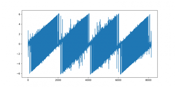
You got it. :) We set up a testbench for the FPGA and fed in a set of test data. We ran the FFT on the FPGA and compared the results with the FFT I was generating using python's numpy.fft.rfft. We created a plot of the phase differences between each frequency bin in the spectrum. You can clearly see the phase walk. The plot shows the phase angle differences with 4 increasing ramps. I talked more with the FPGA guys and found out we are we are using a streaming FFT with 4 channels. Each successive sample in the time series is rotated across the 4 FFT channel inputs.
Thanks for the help. I showed this plot to our physicist and he said we can create a map of phasors that will convert the FPGA coefficients to the regular 8192 sample time series I am using.
I didn't fully understand your description, but please note that the ideal way to fix this is in the time domain (by aligning the samples fed to your software FFT to match the way they are being fed to the FPGA FFT) and not in the frequency domain (by correcting the phases afterwards).
The main reason I say this is that whenever we talk about data "shifts" anywhere near an FFT, we are specifically talking about "circular shifts". In your case, I am pretty sure you just have a linear time offset. As long as the shift size is much smaller than the FFT size, circular and linear shifts will look similar, but they are not the same.
If you don't know the time offset (or it changes from run to run) then you can use the phase gradient (which you plotted) to estimate the time offset. This estimate should then be used to shift the software input data (linearly, in the time domain) and recalculate the software FFT(s) with the correct alignment.
Thanks for the continued thought about my problem. We came to the same conclusion.
The FPGA engineer determined the trigger starting the FFT was one clock cycle early causing us to be off by 4 time samples -> 4 ns. (The ADC sends 4 samples in parallel) We fixed the trigger and now it is working well.
Thanks again
I asked our DSP guy about this and he thinks it is worth checking. He suggested putting in a test signal and looking for the phase walk. Do you have any ideas on the best way to approach testing this? He thinks we can figure out how to model the time-domain shift and reproduce it in the python FFT. In the end I have to compute a DTFT at the locations of interest in my c++/GPU code that has the same phase as what I am getting from the FPGA. Thanks for the idea.
Based on what you’ve posted, I’m leaning towards this as well. Given the same input data, any FFT damn well better have the same output, save possible scaling differences which would not affect phase. Very clever to note that a time shift would result in the same magnitude data, and given the magnitude responses are the same, this feels like the only reasonable explanation

Hello Jutin,
I have noticed that the FFT core (from Xilinx) in the FPGA can return the data in reverse order (not to be confued with bit-reversed order). Therefore try flipping the order of the FFT output.

It is likely your real input changes phase due to oscillators or test setup. Can you confirm that input is at same phase as you expect or is changing?

Does the NP FFT account for real signal time differences in the ADC acquisition? This could be where the phase difference's are.
We think we have the same time series for both the FPGA FFT and the NP FFT. The FPGA sends me the coefficients it calculates and the time series. I thought that any FFT, no matter the implementation, would result in the same phasors when operating on the same time series. Thanks for the idea

I'm skeptical of a delay because your are just taking the same samples as the FPGA after whatever delays may have occurred, so both systems use the same delay. However, if the FPGA divides the data into blocks and then processes those blocks in a different order than you do, you will get the same magnitude with random phases. You will also get energy in the 4th or 8th bin (eg, if the data is divided into 4 or 8 chunks) due to the added discontinuity at the new boundaries (like leakage, but on a block basis).
Are the phase differences regular? Is it possible that it's just a case of misinterpretation of what happens when the phase vector rotates past a multiple of 360 degrees - or rotates the wrong way, giving negative (but correct) values?
I mention this as a previous victim of both effects...


