


So I'm currently working on preparatory lab tasks, which, unfortunately, I cannot solve.
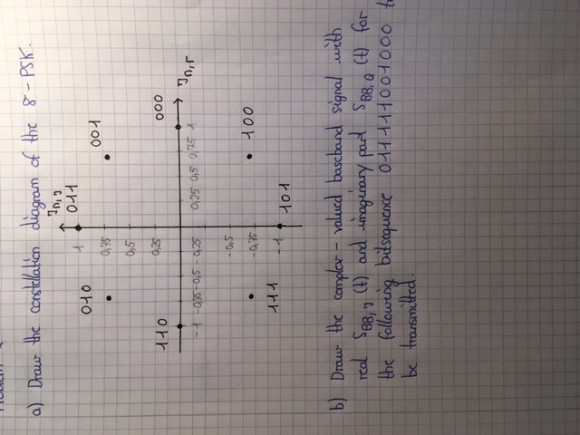
For an 8-PSK modulation I consider the bit sequence 011 111 001 000 , which is to be transmitted. I am asked to draw the complex-valued baseband signal with real $S_BB,I (t)$ and imaginary $S_BB,Q (t)$.
So what I understand is this: The bit sequence is divided into blocks of 3 bits, since we're talking about 8-PSK. Each of these blocks is assigned to a complex-valued modulation symbol which will then be multiplied by a rectangular pulse. But how do I know the value of the modulation symbol? I mean for example the symbol which is completely real and has phase 0 could be assigned to the real value 1. Do I get to choose that? Anyways, I assume I do. What value does the symbol with phase 45° have then? it would have a real and an imaginary part, which are both a little bit smaller than 0.75. I don't understand this, please help!!
Your are asking for the constellation diagram.
There are standards, but the important issue is to use a Gray code in order for small errors to only flip one bit. So, If you want 000 to map to 1, then going around the circle you should map 001 011 010 110 111 101 100 and return to 000.
This will be as good as any other mapping. Obviously, if you have to interwork with someone else's implementation than you have to agree on the mapping.
Y(J)S
Yeah, the constellation diagram is the first part of the task. The modulation symbols have to be labelled as you can see in the photograph. But I have no clue about the second question. Oh, also in the constellation diagram I don't know what values to write on the axes. The values which have been written with pencil are just guesses.
And btw the normalized signal power S = 1. Don't know what that's suppossed to tell me either.

And even though I've re-read your original post, I have no clue what your second question is!!!
Your constellation diagram would work. A normalized signal power of 1 means that you're simplifying, because you don't really care what the signal power is at this point (signal/noise ratio means something on the receive end, but even there, the absolute signal power doesn't mean much).
Just to complicate your life, note that PSK modulation schemes often use differential signaling -- i.e., 000 would be encoded by the phase staying the same, 001 by the phase advancing 45 degrees, 111 by the phase moving back 45 degrees, etc. This makes the system less vulnerable to phase slips in the carrier synchronization, at the cost of increasing (roughly doubling, if I remember correctly) the bit error rate for a given SNR.

I'm certainly not an expert on this, but maybe I can shed some light. BTW I apologize if I misinterpret your question.
You notice that the values in your constellation diagram form a circle with radius 1 (this is what you want). Therefore the 45 degree values for the real and imaginary parts can be calculated using the Pythagorean theorem, sine/cosine, etc (the hypotenuse is always 1). Since the angle is 45 degrees (and 135, 225, 315) then you know that both real and imaginary values will be equal in magnitude (though not in sign for 135 and 315 degrees).
What this means in terms of phase shift keying (PSK) is that for a particular CW reference signal, your generated signal will sometimes be in phase (0 degrees), out of phase (180 degrees phase shift) or in quadrature (90 or 270 degrees), depending on the data sequence.
Therefore a correlation with the CW reference signal would yield +1 for the 0 degree transmitted signal, -1 for the 180 degree transmitted signal, etc. Also, a correlation with a quadrature CW reference signal (90 degrees shifted from the original) would yield +1 for the 90 degree transmitted signal, -1 for the 270 degree transmitted signal, etc. This would be a method of recovering the data at a receiver, which I know is not what you're doing, but hopefully it helps with your understanding.
Tim

You have 8 possible complex values, the in-phase signal corresponds to the real part and quadrature signal to the imaginary part.
The decoding symbol decision will be made on the receiver side based on the phase shift and amplitude values.
Simon

Hello,
Like others have said, I'm not quite sure what your question is. But assuming that you just want the I/Q values and the constellation below is correct, label the points P0, P1, ..., P7 clockwise around the circle with P0 being at the top in the imaginary position. So your given bit sequence would be P0, P5, P1, P2 = pi/2, 5*pi/4, pi/4, 0.
So your mapped I/Q values at baseband symbol rate is x(t) = {[cos(P0) + i*sin(P0)], [cos(P5) + i*sin(P5)], , }.
Note that for transmission these values are then passed through an interpolation filter so that a smooth waveform is produced for modulation. Usually that is some kind of Nyquist filter but that is a story for another day.
Best Regards,
Mark Napier


