


First of all, let me warn you, I'm a neophyte on this. Did my EE degree 40 years ago, before FFT's were rediscovered.
I am trying to reduce frequency bin "leakage" from the I/Q output and #FFT of an #SDR receiver. Using a Blackman-Harris 7 point window helps a lot, but I was hoping thatby doing a window-presum (a.k.a. Polyphase, WOLA) it would tighten up even more. However, with my simple implementation, it made things worse. I'm hoping you experts can point me to the error of my ways.
First of all, here's a code snippet without window-presum that works right:
Fourier.ApplyFFTWindow(_fftPtr, _fftWindowPtr, _fftBins);
Fourier.ForwardTransform(_fftPtr, _fftBins);
Fourier.SpectrumPower(_fftPtr, _fftSpectrumPtr, _fftBins, compensation);
_fftPtr is a Complex* pointer to a 32768 point sample, so _fftBins = 32768.
Works great, with a little bin leakage.
And the code that makes things worse:
Fourier.ApplyFFTWindow(_fftPtr, _fftWindowPtr, _fftBins);
// break up the original 32768 point sample into 4 _fftPt sample arrays.
for (i = 0; i < 4; i++)
{
Utils.Memcpy(_fftPt[i], _fftPtr + (i * _fftBins / 4), _fftBins / 4);
}
// add the points from each array together. Write the result back into _fftPtr
Fourier.AddPolyphase(_fftPtr, _fftPt[0], _fftPt[1], _fftPt[2], _fftPt[3], _fftBins / 4);
Fourier.ForwardTransform(_fftPtr, _fftBins / 4);
Fourier.SpectrumPower(_fftPtr, _fftSpectrumPtr, _fftBins / 4, compensation);
and
public static void AddPolyphase(Complex* totalbuffer, Complex* buffer0, Complex* buffer1, Complex* buffer2, Complex* buffer3, int length)
{
for (var i = 0; i < length; i++)
{
totalbuffer[i].Real = (buffer0[i].Real + buffer1[i].Real + buffer2[i].Real + buffer3[i].Real) * (float)0.25;
totalbuffer[i].Imag = (buffer0[i].Imag + buffer1[i].Imag + buffer2[i].Imag + buffer3[i].Imag) * (float)0.25;
}
}
Where did I got wrong ?
Thanks,
Steve

Hi Steve,
Check out this page: https://casper.berkeley.edu/wiki/The_Polyphase_Fil...
I don't see the sync function multiply in your code, but I don't understand your code either. It looks like they break up the sync function to be such that 1/4 of the window is a zero crossing from either end. I bet the magic is in the structure of that sync window - if you use multiple zero crossings you would add more zones. The center section is also interesting, it kind of swaps the time domain data front to back.
This seems like an interesting trick. I want to study this some more because it might be really useful!
Dr. mike

Whatever you believe you're doing, I don't think you're actually doing it.
You're basically taking one sequence, windowing it, chopping it into four, adding them, and then taking the FFT of the result.
First, the value of windowing is that it smooths out the transitions at the ends of the data set that you're taking the FFT of. When you chop the thing up into four and add, you're making new edges. So if you did this at all, you'd want to chop, then window, then add. Or chop, add, and window.
Second, I'm not sure what the chop-and-add step is supposed to do. If you're trying to make an easily-computed low-pass filter, you missed the target. Adding sets of four consecutive samples and then downsampling would be a way to decimate (with debatable benefits, but it would mean something at least). Even there you'd probably want to filter, decimate, and then window, just to reduce processing time if nothing else.

Hi,
The first sentence of your second paragraph really puzzles me. I'll assume that what you mean is that you're trying to reduce the leakage in the results of performing an FFT of some complex-valued (I/Q) time-domain sequence.
My first question is, Do you really need to reduce the leakage in the FFT's output? Spectral leakage is normally only a problem when we're trying to measure the power of a low-power narrowband spectral component when that component is located near a high-level spectral component. And the spectral leakage from the high-level component is "swamping out" (masking) the low-level spectral component of interest. Steve, is that your situation?
The WOLA (a.k.a, window presum) processing scheme is a clever technique used to implement a channelized spectrum analyzer using the FFT. (I cover that scheme in Chapter 13 of my DSP book.) The frequency response of adjacent FFT bins look like the following:
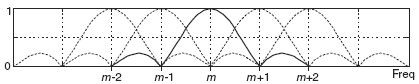
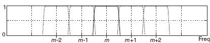
which makes for a poor spectrum analyzer due to high sidelobes and significant mainlobe overlap. The clever WOLA scheme enables the implementation of an FFT-based spectrum analyzer whose freq-domain performance looks like the following:
Steve, I can't read your code, so I don't know what your code is doing. Having said that, I don't see how the WOLA scheme relates to your perceived "FFT output leakage reduction" problem.
If you'd like to read my description of the WOLA scheme, send me a private e-mail at R_dot_Lyons_at_ieee_dot_org.
Hi Lyons! In which section of your DSP book, chapter 13, I can find more information about WOLA? I can't discover such abbreviation there. The algorithm described in https://casper.berkeley.edu/wiki/The_Polyphase_Fil... is clear but I don't understand why it works (the chopping and adding part).

Much of understanding this, I believe, boils down to the fact that unweighted / unwindowed finite-length sequences have an underlying sinc or (perhaps more accurately) circular sinc component. These can be added judiciously to form "better" results with the understanding that the width of the sincs cannot be reduced. And, similarly and to a large degree at least, the sharpness of decay on the edges of their sums. But, much-improved responses can be obtained through summations of shifted sincs - subject to those constraints. Windowing methods do this - at least conceptually .. so it's fairly easy to understand. The rest boils down to implementation.
Much of understanding this, I believe, boils down to the fact that unweighted / unwindowed finite-length sequences have an underlying sinc or (perhaps more accurately) circular sinc component. These can be added judiciously to form "better" results with the understanding that the width of the sincs cannot be reduced. And, similarly and to a large degree at least, the sharpness of decay on the edges of their sums. But, much-improved responses can be obtained through summations of shifted sincs - subject to those constraints. Windowing methods do this - at least conceptually .. so it's fairly easy to understand. The rest boils down to implementation.
Look at Figure 3 of https://casper.berkeley.edu/wiki/The_Polyphase_Fil...
They apply a sinc function window to x(t), then chop up the result into 4 time segments, then sum the individual components. I'm not sure why a sync function was used. Then there is http://www.embedded.com/design/real-time-and-perfo... from Rick Lyons. Again, I'm not sure how and why that window filter was chosen.
Thanks for all the responses.
Steve
The reason to use a sync function is because it is the Fourier transform of a square function. So if you multiply by the the sync and then do an FFT you get a square result - which is what you want in the frequency domain. The reason they chop it where they do is because it goes to zero at the chop points - except in the center where it is max. When all the data is combined, you get two lobes of the sync which go from zero to max to zero and two lobes with one going from min to max and the other from max to min. The combination looks like a uniform distribution. So it makes sense from an intuitive perspective. The result is square, and the FFT result unwinds the sync into square so you get sharp edges in the frequency domain.
Dr. mike
Thanks Dr. mike for the intuitive explanation. Still it should work if the signal is split into more than 4 blocks in which case the combination will not look so uniform. Krasin
Thanks for the link Steve. Krasin
But there are no shifted sinks - just a single sinc that multiplies the whole sequence before chopping. Now I see that it will modify the spectrum of the signal before the next processing steps which involve aliasing in time domain.
>My first question is, Do you really need to reduce the leakage in the >FFT's output? Spectral leakage is normally only a problem when we're >trying to measure the power of a low-power narrowband spectral component >when that component is located near a high-level spectral component. And >the spectral leakage from the high-level component is "swamping out" >(masking) the low-level spectral component of interest. Steve, is that >your situation?
Yes, that is precisely the problem I am trying to solve. The situation is a large number of discrete, close-spaced signals, having large power variations (from 0 to 60 dB variation from from signal-to-signal). I am presenting a real-time, waterfall display of the signals (time on x-axis, frequency on y-axis).
n2ic,
Dr. Mike's August 16 reply is a good one. I hope it made sense to you.
Regarding your "precisely the problem" reply, it seems to me that your value for N must be large enough so that a large signal and a neighboring small "signal of interest" will NOT be within a single FFT output bin.
What I was trying to describe is that the "square in the frequency domain" is made up of a bunch of narrow frequency-shifted sincs that relate to the entire length of the time window. These are combined to maximize the edge slopes and minimize the leakage outside the "square". If that's done in the frequency domain then the time domain version will *look like* a much narrower sinc in time of course...
If all you do is use a rectangular window in the frequncy domain then what you get is a sinc shape in time. I think that's what drmike was referring to more or less. If you optimize the "rectangle" then you get something somewhat different in time than a plain old sinc.
Rick's comment about N goes right along with this. You'd like to have a number of narrow sincs (let's say "M" of them) to build the rectangle in frequency. For things to be split into B bands, you then need N=M*B.
Okay - I finally have this figured out and working.
It turns out that in my application, the presum window function is not critical. Any reasonably good window function, such as a Blackman-Harris 7 works well. The important thing is the summing operation. It helps to not have a nasty bug in your code !
Thanks for all the suggestions.
Steve


