It turns out that analog allpass filters are considerably simpler
mathematically than digital allpass filters (discussed in
§B.2). In fact, when working with digital allpass filters,
it can be fruitful to convert to the analog case using the bilinear
transform (§I.3.1), so that the filter may be manipulated in the
analog  plane rather than the digital
  plane. The analog case
is simpler because analog allpass filters may be described as having a
zero at
plane. The analog case
is simpler because analog allpass filters may be described as having a
zero at
 for every pole at
  , while digital allpass
filters must have a zero at
, while digital allpass
filters must have a zero at
 for every pole at
  .
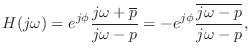
In particular, the transfer function of every first-order analog
allpass filter can be written as
.
In particular, the transfer function of every first-order analog
allpass filter can be written as
where

is any constant phase offset.
To see why

must be allpass, note that
its
frequency response is given by
which clearly has modulus 1 for all

(since
). For real allpass filters,
complex poles must occur in conjugate pairs, so that the ``allpass
rule'' for
poles and zeros may be simplified to state that a zero is
required at
minus the location of every pole,
i.e., every
real first-order allpass filter is of the form
and, more generally, every real allpass transfer function can be factored as
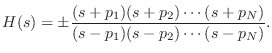 |
(E.14) |
This simplified rule works because every complex pole

is
accompanied by its conjugate

for some
![$ k\in[1:N]$](http://www.dsprelated.com/josimages_new/filters/img1918.png)
.
Multiplying out the terms in Eq. (E.14), we find that the numerator
polynomial
(E.14), we find that the numerator
polynomial  is simply related to the denominator polynomial
  :
:
Since the roots of
must be in the left-half
-plane for
stability,
must be a
Hurwitz polynomial, which implies
that all of its coefficients are nonnegative. The polynomial
can be seen as a

-rotation of
in the
plane; therefore,
its roots must have non-positive real parts, and its coefficients form
an alternating sequence.
As an example of the greater simplicity of analog allpass filters
relative to the discrete-time case, the graphical method for computing
phase response from poles and zeros (§8.3) gives immediately
that the phase response of every real analog allpass filter is equal
to twice the phase response of its numerator (plus when
the frequency response is negative at dc). This is because the angle
of a vector from a pole at to the point  along the
frequency axis is minus the angle of the vector from a zero at
along the
frequency axis is minus the angle of the vector from a zero at
 to the point
  .
.
Lossless Analog Filters
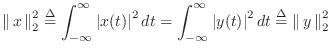
As discussed in §B.2, the an allpass filter can be defined
as any filter that preserves signal energy for every input
signal  . In the continuous-time case, this means
where

denotes the output signal, and

denotes the
L2 norm of

. Using the
Rayleigh energy theorem
(
Parseval's theorem) for
Fourier transforms [
87],
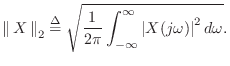
energy preservation can be expressed in the
frequency domain by
where

and

denote the Fourier transforms of

and
, respectively,
and frequency-domain L2
norms are defined by
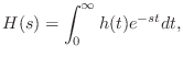
If

denotes the
impulse response of the
allpass
filter, then its
transfer function
is given by the
Laplace transform of

,
and we have the requirement
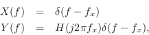
Since this equality must hold for every input signal
, it must be
true in particular for complex
sinusoidal inputs of the form
, in which case [
87]
where  denotes the Dirac ``delta function'' or continuous
impulse function (§E.4.3). Thus, the allpass condition becomes
denotes the Dirac ``delta function'' or continuous
impulse function (§E.4.3). Thus, the allpass condition becomes
which implies
 |
(E.15) |
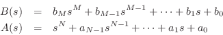
Suppose

is a rational analog filter, so that
where
and
are polynomials in
:
(We have normalized so that is monic ( ) without
loss of generality.) Equation (E.15) implies
) without
loss of generality.) Equation (E.15) implies
If

, then the allpass condition reduces to
,
which implies
where
is any real phase constant. In other words,

can be any unit-modulus
complex number. If

, then the
filter is allpass provided
Since this must hold for all
, there are only two solutions:
 and
and  , in which case
 for all .
-
 and , i.e.,
Case (1) is trivially allpass, while case (2) is the one discussed above
in the introduction to this section.
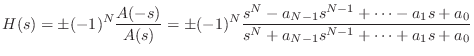
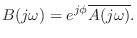
By analytic continuation, we have
If
is real, then
, and we can write
To have
, every
pole at
in
must be canceled
by a zero at
in

, which is a zero at
in
.
Thus, we have derived the simplified ``allpass rule'' for real analog
filters.
Next Section: IntroductionPrevious Section: Quality Factor (Q)