


Wave Impedance in a Cone
From Eq.![]() (C.146) we have that the traveling-wave solution of the
wave equation in spherical coordinates can be expressed as
(C.146) we have that the traveling-wave solution of the
wave equation in spherical coordinates can be expressed as
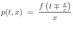

i.e., it can be expressed in terms of its own time derivative. This is a general property of any traveling wave.
![\includegraphics[width=\twidth]{eps/fconeparams}](http://www.dsprelated.com/josimages_new/pasp/img4294.png)
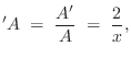
Referring to Fig.C.46, the area function ![]() can be
written for any cone in terms of the distance from its apex as
can be
written for any cone in terms of the distance from its apex as
Substituting the logarithmic derivative of ![]() and
and ![]() from
Eq.
from
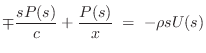
Eq.![]() (C.150) into the momentum-conservation equation
Eq. (C.148) yields
(C.150) into the momentum-conservation equation
Eq. (C.148) yields
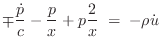
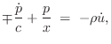
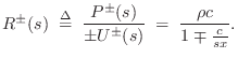
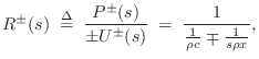
We can now solve for the wave impedance in each direction, where
the wave impedance may be defined (§7.1)
as the Laplace transform of the traveling pressure divided by
the Laplace transform of the corresponding traveling velocity wave:
 |
|||
 |
We introduce the shorthand
Note that for a cylindrical tube, the wave impedance in both directions is
![]() , and there is no frequency dependence. A wavelength
or more away from the conical tip, i.e., for
, and there is no frequency dependence. A wavelength
or more away from the conical tip, i.e., for
![]() ,
where
,
where ![]() is the spatial wavelength, the wave impedance again approaches
that of a cylindrical bore. However, in conical musical instruments,
the fundamental wavelength is typically twice the bore length, so the
complex nature of the wave impedance is important throughout the bore and
approaches being purely imaginary near the mouthpiece. This is
especially relevant to conical-bore double-reeds, such as the bassoon.
is the spatial wavelength, the wave impedance again approaches
that of a cylindrical bore. However, in conical musical instruments,
the fundamental wavelength is typically twice the bore length, so the
complex nature of the wave impedance is important throughout the bore and
approaches being purely imaginary near the mouthpiece. This is
especially relevant to conical-bore double-reeds, such as the bassoon.
Writing the wave impedance as
Up to now, we have been defining wave impedance as pressure divided by particle velocity. In acoustic tubes, volume velocity is what is conserved at a junction between two different acoustic tube types. Therefore, in acoustic tubes, we define the wave impedance as the ratio of pressure to volume velocity
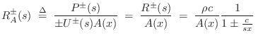
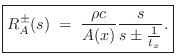
This is the wave impedance we use to compute the generalized reflection and transmission coefficients at a change in cross-sectional area and/or taper angle in a conical acoustic tube. Note that it has a zero at
In this case, the equivalent mass is
![]() . It would perhaps be more satisfying if the equivalent mass in
the conical wave impedance were instead
. It would perhaps be more satisfying if the equivalent mass in
the conical wave impedance were instead
![]() which is the
mass of air contained in a cylinder of radius
which is the
mass of air contained in a cylinder of radius ![]() projected back to
the tip of the cone. However, the ``acoustic mass'' cannot be
physically equivalent to mechanical mass. To see this, consider that
the impedance of a mechanical mass is
projected back to
the tip of the cone. However, the ``acoustic mass'' cannot be
physically equivalent to mechanical mass. To see this, consider that
the impedance of a mechanical mass is ![]() which is in physical units
of mass per unit time, and by definition of mechanical impedance this
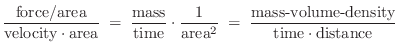
equals force over velocity. The impedance in an acoustic tube, on the
other hand, must be in units of pressure (force/area) divided by
volume velocity (velocity
which is in physical units
of mass per unit time, and by definition of mechanical impedance this
equals force over velocity. The impedance in an acoustic tube, on the
other hand, must be in units of pressure (force/area) divided by
volume velocity (velocity ![]() area) and this reduces to
area) and this reduces to
The real part of the wave impedance corresponds to transportation of wave
energy, the imaginary part is a so-called ``reactance'' and does not
correspond to power transfer. Instead, it corresponds to a ``standing
wave'' which is created by equal and opposite power flow, or an
``evanescent wave'' (§C.8.2), which is a non-propagating,
exponentially decaying, limiting form of a traveling wave in which the
``propagation constant'' is purely imaginary due to being at a
frequency above or below a ``cut off'' frequency for the waveguide
[295,122]. Driving an ideal mass at the end of a
waveguide results in total reflection of all incident wave energy
along with a quarter-cycle phase shift. Another interpretation is
that the traveling wave becomes a standing wave at the tip of the
cone. This is one way to see how the resonances of a cone can be the
same as those of a cylinder the same length which is open on
both ends. (One might first expect the cone to behave like a
cylinder which is open on one end and closed on the other.) Because
the impedance approaches a purely imaginary zero at the tip, it looks
like a mass (with impedance
![]() ). The ``piston of air'' at
the open end similarly looks like a mass
[285].
). The ``piston of air'' at
the open end similarly looks like a mass
[285].
Next Section:
More General One-Parameter Waves
Previous Section:
Momentum Conservation in Nonuniform Tubes


