


Flanging
Flanging is a delay effect that has been available in recording studios since at least the 1960s. Surprisingly little literature exists, although there is some [32,429,59,17,104,242].6.1
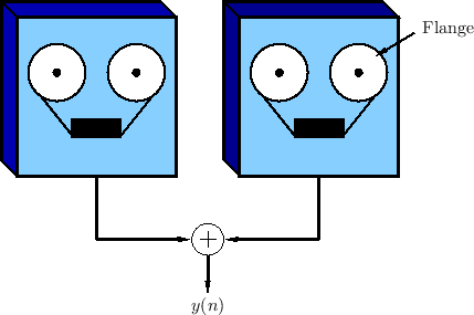
The term ``flanging'' is said to have arisen from the way the effect was originally achieved by two tape machines set up to play the same tape in unison, with their outputs added together (mixed equally), as shown in Fig.5.2. To achieve the flanging effect, the flange of one of the supply reels is touched lightly to make it play a littler slower. This causes a delay to develop between the two tape machines. The flange is released, and the flange of the other supply reel is touched lightly to slow it down. This causes the delay to gradually disappear and then begin to grow again in the opposite direction. The delay is kept below the threshold of echo perception (e.g., only a few milliseconds in each direction). The process is repeated as desired, pressing the flange of each supply reel in alternation. The flanging effect has been described as a kind of ``whoosh'' passing subtly through the sound.6.2The effect is also compared to the sound of a jet passing overhead, in which the direct signal and ground reflection arrive at a varying relative delay [59]. If flanging is done rapidly enough, an audible Doppler shift is introduced which approximates the ``Leslie'' effect commonly used for organs (see §5.9).
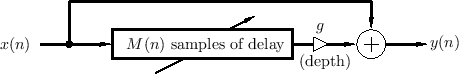
Flanging is modeled quite accurately as a feedforward comb filter, as
discussed in §2.6.1, in which the delay ![]() is varied
over time. Figure 5.3 depicts such a model. The input-output
relation for a basic flanger can be written as
is varied
over time. Figure 5.3 depicts such a model. The input-output
relation for a basic flanger can be written as
where
As shown in Fig.2.25, the frequency response of Eq.![]() (5.1)
has a ``comb'' shaped structure. For
(5.1)
has a ``comb'' shaped structure. For ![]() , there are
, there are ![]() peaks in the frequency response, centered about frequencies
peaks in the frequency response, centered about frequencies
As is evident from Fig.2.25, at any given time there are ![]() notches in the flanger's amplitude response (counting positive-
and negative-frequency notches separately). The notches are thus
spaced at intervals of
notches in the flanger's amplitude response (counting positive-
and negative-frequency notches separately). The notches are thus
spaced at intervals of ![]() Hz, where
Hz, where ![]() denotes the sampling
rate. In particular, the notch spacing is inversely
proportional to delay-line length.
denotes the sampling
rate. In particular, the notch spacing is inversely
proportional to delay-line length.
The time variation of the delay-line length ![]() results in a
``sweeping'' of uniformly-spaced notches in the spectrum. The
flanging effect is thus created by moving notches in the
spectrum. Notch motion is essential for the flanging effect. Static
notches provide some coloration to the sound, but an isolated notch
may be inaudible [139]. Since the steady-state sound
field inside an undamped acoustic tube has a similar set of
uniformly spaced notches (except at the ends), a static row of notches
tends to sound like being inside an acoustic tube.
results in a
``sweeping'' of uniformly-spaced notches in the spectrum. The
flanging effect is thus created by moving notches in the
spectrum. Notch motion is essential for the flanging effect. Static
notches provide some coloration to the sound, but an isolated notch
may be inaudible [139]. Since the steady-state sound
field inside an undamped acoustic tube has a similar set of
uniformly spaced notches (except at the ends), a static row of notches
tends to sound like being inside an acoustic tube.
Flanger Speed and Excursion
As mentioned above, the delay-line length ![]() in a digital flanger
is typically modulated by a low-frequency oscillator (LFO).
The oscillator waveform is usually triangular, sinusoidal, or
exponential (triangular on a log-frequency scale). In the sinusoidal
case, we have the following delay variation:
in a digital flanger
is typically modulated by a low-frequency oscillator (LFO).
The oscillator waveform is usually triangular, sinusoidal, or
exponential (triangular on a log-frequency scale). In the sinusoidal
case, we have the following delay variation:
Flanger Depth Control
To obtain a maximum effect, the depth control, ![]() in Fig.5.3,
should be set to 1. A depth of
in Fig.5.3,
should be set to 1. A depth of ![]() gives no effect.
gives no effect.
Flanger Inverted Mode
A different type of maximum depth is obtained for ![]() . In this
case, the peaks and notches of the
. In this
case, the peaks and notches of the ![]() case trade places. In
practice, the depth control
case trade places. In
practice, the depth control ![]() is usually constrained to the interval
is usually constrained to the interval
![]() , and a sign inversion for
, and a sign inversion for ![]() is controlled separately using a
``phase inversion'' switch.
is controlled separately using a
``phase inversion'' switch.
In inverted mode, unless the delay ![]() is very large, the bass
response will be weak, since the first notch is at dc. This case
usually sounds high-pass filtered relative to the ``in-phase'' case
(
is very large, the bass
response will be weak, since the first notch is at dc. This case
usually sounds high-pass filtered relative to the ``in-phase'' case
(![]() ).
).
As the notch spacing grows very large (![]() shrinks), the amplitude
response approaches that of a first-order difference
shrinks), the amplitude
response approaches that of a first-order difference
![]() , which approximates a differentiator
, which approximates a differentiator
![]() . An ideal differentiator eliminates dc and provides
a progressive high-frequency boost rising 6 dB per octave
(specifically, the amplitude response is
. An ideal differentiator eliminates dc and provides
a progressive high-frequency boost rising 6 dB per octave
(specifically, the amplitude response is
![]() ).
).
Flanger Feedback Control
Many modern commercial flangers have a control knob labeled ``feedback'' or ``regen.'' This control sets the level of feedback from the output to the input of the delay line, thereby creating a feedback comb filter in addition to the feedforward comb filter, in the same manner as in the creation of a Schroeder allpass filter in §2.8.1 (see Fig.2.30).
Summary of Flanging
In view of the above, we may define a flanger in general as any filter which modulates the frequencies of a set of uniformly spaced notches and/or peaks in the frequency response. The main parameters are
- Depth
![$ g\in[0,1]$](http://www.dsprelated.com/josimages_new/pasp/img1245.png) -- controlling notch depth
-- controlling notch depth
- Speed
 -- speed of notch movement
- Phase -- switch to subtract instead of adding the direct signal with the delayed signal
- Average Delay

- Excursion or Sweep
 -- amount by which the delay-line grows or shrinks
- Feedback or Regeneration
 -- feedback coefficient from output to input
Note that flanging provides only uniformly spaced notches.
This can be considered non-ideal for several reasons. First, the ear
processes sound over a frequency scale that is more nearly logarithmic
than linear [459]. Therefore, exponentially spaced
notches (uniformly spaced on a log frequency scale) should sound more
uniform perceptually. Secondly, the uniform peaks and notches of the
flanger can impose a discernible ``resonant pitch'' on the program
material, giving the impression of being inside a resonant tube.
Third, when ![]() (inverted flanging), it is possible for a periodic
tone to be completely annihilated by harmonically spaced notches if
the harmonics of the tone are unlucky enough to land exactly on a
subset of the harmonic notches. In practice, exact alignment is
unlikely; however, the signal loudness can be modulated to a possibly
undesirable degree as the notches move through alignment with the
signal spectrum. For this reason, flangers are best used with
noise-like or inharmonic sounds. For harmonic signals, it makes sense
to consider methods for creating non-uniform moving notches.
(inverted flanging), it is possible for a periodic
tone to be completely annihilated by harmonically spaced notches if
the harmonics of the tone are unlucky enough to land exactly on a
subset of the harmonic notches. In practice, exact alignment is
unlikely; however, the signal loudness can be modulated to a possibly
undesirable degree as the notches move through alignment with the
signal spectrum. For this reason, flangers are best used with
noise-like or inharmonic sounds. For harmonic signals, it makes sense
to consider methods for creating non-uniform moving notches.
A Faust software implementation of flanging may be found in the file effect.lib within the Faust distribution [154,170]. The Faust programming example phaser_flanger.dsp may be run to hear the effect on a test signal and experiment with its parameters in real time.
Next Section:
Phasing
Previous Section:
Doubling and Slap-Back


