


Hi all,
Suppose I have an input signal \( x[n] \) of length \( N \), an FIR filter \( h[n] \) of length \( M \), and a window function \( w[n] \) of length \( N \). And their frequency domain expressions via Fourier transform are \( X[f], H[f], W[f]\), respectively.
From my understanding, if I consider a convolution by using an overlap-add procedure, it can be done by using a circular convolution between \( X[f] \) and \( H[f] \) (both are of length \( N + M - 1\) to avoid aliasing issue).
Here is my question.
If I consider using the window function \( w[n] \), I am not sure how to set the length of \( w[n] \). The pseudo-code below which is only for one segment is how I implemented in MATLAB
%
% x : input signal of length Nx1
% h : filter of length Mx1
% w : window of length Nx1
% y : output signal (filtered signal) of length (N+M-1)x1
% clength: the length of the convolution -- N+M-1

%  ---------------------------------------------
clength = N+M-1;
X = fft(w.*x, clength);   % of length N+M-1 x 1
H = fft(h, clength);      % of length N+M-1 x 1
Y = X.*H;                 % of length N+M-1 x 1
As you can see from the pseudo-code above, I can implement until \( Y \) which is the multiplication between \( X[f] \) and \( H[f] \); hence, \( Y \) also is of length \( N+M-1 \). But since the window is of length \( N \), I cannot calculate inverse FFT in order to have the filtered output signal.
I've already tried to calculate as
y = w.*ifft(Y, N);
but, this causes some audible artifact.
I'll appreciate if anyone give any comments on this.
#MATLAB #convolution #FFT

Having just spent the last month working on a project that used FFT/IFFT for a slightly different purpose with overlap/add, I found Julius Smith's book extremely helpful to remind myself of the basic mechanics of this:
https://www.dsprelated.com/freebooks/sasp/Overlap_...
Particularly in getting the window size/symmetry correct, and the funny about Matlab's window functions.
I should have added that I find using a ramp waveform is extremely helpful to find that occasional sample where you're "off by 1" and then debug the code - if you do an A-B to compare input and output the oddball sample usually becomes pretty obvious, and/or you can include some test code right in the program. Of course you need a (temporary) filter that isn't going to change the waveshape very much.
It helped me find the (literally) one in a million samples where I was off by a tiny bit (like -80 dB off). Tough to find those looking at FFT or listening.
Hello lamabrew,
Thanks for your answer! I first have to have a look about the page you shared, it must be a very good starting point for understanding all the basic mechanics.
By the way, can you elaborate the additional answer you posted below since I can't follow what you wrote there. I definitely agree with you using a test function so that you can check your implementation is correct or not. Is the ramp waveform a sawtooth or triangle waveform?
Bests,
ctlee
Hi @ctlee,
I usually find myself using a ramp as the fast + to - transition can provide a good marker for measuring time, i.e. if I want to get the exact frequency I can look for (let's say) 1000 + to - transitions and take the number of samples and depending on the details you can get an accurate frequency without using FFT. Again this is with the idea of creating a test harness around your code during development.
Of course there's some assumptions about the filter's affect on the edge, is the waveform periodic at the sample rate, etc. On that last point you want to test both ways, something that is related to the sample rate and something that isn't.
Likewise a monotonically increasing ramp can be independently calculated/tested for in the code (again with a filter that doesn't change it much) to look for problems.
Though if the only thing you're doing is filtering via FFT/IFFT it's less likely that there's errors that span more than a few windows of data; my comment should have clarified I was thinking more of a system test. And of course really any waveform can be used, for me I find a ramp easier to spot issues.
Regards,
Brewster

Hey @ctlee,
Up to the point you have implemented everything is alright (I assume the fft function pads with zeros if the length of the asked transform is longer than the given vector).
The thing is that you don't have to multiply again with the window in order to go back to the time-domain representation. So, after doing the frequency-domain multiplication (which is equivalent to a time-domain convolution) you can just "ifft" the vector.
One thing you should take care of is to make sure you will use an ovelap-add algorithm and keep the last M-1 samples of your time-domain signal to be added to the time-domain signal (the one that will result from the ifft) of the next frame/window.
Hope this makes sense. If you need additional help of clarifications please don't hesitate to ask.
Best,
A.
P.S.: According to MATLAB help, what you do in your implementation if you perform the ifft(Y, N) is that you actually discard some part of the spectrum (because N, is shorter than the length of your frequency representation, which is N+M-1). Thus, you will most definitely end up with the WRONG time-domain signal (part of the artifacts you get is due to this "truncation" of the spectrum and part of it is due to the extra window-function applied before you perform the ifft).
hello CTLEE,
Attached is a matlab HW solution and demonstration I used for my DSP class,,, It performs a convolution of a 100000 data sequence (two sinusoids) with a 415 tap Low-pass Fir Filter. It performs 5 versions of the task and compares time required to do each. It outputs a graph showing actual times. the fast convolution uses overlap and discard. Using a low frequency sinewave is very telling: you can immediately see if there is a boundary induced error because the boundaries were not properly chosen. The results are both surprising and interesting.
1. direct convolution
2. matlab filter command
3. task with 1024 point FFT
4. task with 2048 point FFT
5. task with 4096 pint FFT
can answer questions about the code if you have any
fred harris
Hello fred,
Thanks for your code.
I've downloaded and run it immediately.
I'll have a thorough look soon, but it was very helpful to understand which way I have to choose if I'll use filter function in some way.
Bests,
ctlee
p.s. I'm using MATLAB R2017a currently, it returns a warning message about using 'remez' function, so I've changed the line as follows:
%% Originally
h1=remez(414,[0 10 20 500]/500,{'myfrf',[1 1 0 0]},[1 10]);

%% How I used the line above is
h1=firpm(414,[0 10 20 500]/500,[1 1 0 0],[1 10]);
since I got a warning message about using 'remez' and an error message about 'myfrf', so that's why I've changed the code. After editing this line, it shows what you intended in this code.
Thanks for your answer and code!
Hi @ZaellixA,
Thanks for your answer. So far I thought I have to use window function twice (before and after filtering). Why I thought in that way was that I found this overlap-add from audio coding described here (A wikipedia page for Modified discrete cosine transform). Using this, the output signal can be perfectly reconstructed when the window is used twice. This is why I was trying to apply the window function twice.
Now then, I think I need to figure out why they are different. I'll try to see why they work differently!
Bests,
ctlee

if you are after fft convolution versus time domain convolution here is my go:
as an example of fft based convolution targeting equivalent sample values(bit-true) here is what I will do. There is some rounding issue but you can remove it.
n = 100;
m = 200;
a = randn(1,n);
b = randn(1,m);
y1 = conv(a,b);
y2 = ifft(fft(a,n+m-1).* fft(b,n+m-1));
plot(y1); hold
plot(real(y2),'r--')
Hello kaz,
Thanks for the compact code and answer.
I also do the same thing if I have only one segment, since the implementation you gave in the answer above is a very good example to show the comparison between the circular and linear convolutions.
However, what now I am trying to do is WOLA(weighted overlap-add), several challenges arise that I didn't expect. One of them is the question that I posted here.
Bests,
ctlee
but what stops you using correct size window to match ifft output size?
yes, if I revise your implementation as follows, then I can explain what I am trying to look for. Note that the length of a,b could be varied according to the explanation in the reply by @lamabrew
n = 100;
m = 200;
a = randn(n,1);
b = randn(m,1);

% for the simplest
w = hanning(m);

% assume b is the input signal

y1 = conv(a,w.*b);

y2 = ifft(fft(a,n+m-1).* fft(w.*b,n+m-1));

figure
plot(y1); hold on
plot(real(y2),'r--')
plot(y1 - real(y2), 'k')
hold off
In this case, which is applying a hanning window function to the input signal, we can have n+m-1 length of output signal y2 and this is identical to y1 which is the result from the linear convolution.
But if we use this type of window function (link) below:
$$ w[n] = \sin{(\frac{\pi}{M} (n+0.5))} $$
where \(n = {0, \cdots, M-1}\),
you should use this window function twice which is before and after filtering in the frequency domain in order to have a perfect reconstruction. Then the problem I described here arises because of the mismatch of the lengths:
n = 100;
m = 200;
a = randn(n,1);
b = randn(m,1);

% for the simplest
% w = hanning(m);
w = sin((pi/(m))*(linspace(0,(m)-1,(m))+1/2))';

y1 = conv(a,w.*b);

% assume b is the input signal
y2 = real(ifft(fft(a,n+m-1).* fft(w.*b,n+m-1)));

% This cannot be calculated due to the different length.
y2 = w.*y2;

figure
plot(y1); hold on
plot(y2,'r--')
plot(y1 - y2, 'k')
hold off
I tried this with some result
n = 100;
m = 200;
a = randn(n,1);
b = randn(m,1);
% for the simplest
%w = hanning(m);
w1 = sin((pi/(m))*(linspace(0,(m),(m))+1/2))';
w2 = sin((pi/(m+n-1))*(linspace(0,(m+n-1),(m+n-1))+1/2))';
y1 = conv(a,w1.*b);
% assume b is the input signal
y2 = real(ifft(fft(a,n+m-1).* fft(w1.*b,n+m-1)));
% This cannot be calculated due to the different length.
y2 = w2.*y2;
figure
plot(y1); hold on
plot(y2,'r--')
plot(y1 - y2, 'k')
hold off
Hey there,
Well, to be honest I am not very familiar with the Modified Discrete Cosine Transform but in the link you provided I could find this quoted
Note that windows applied to the MDCT are different from windows used for some other types of signal analysis, since they must fulfill the Princen-Bradley condition. One of the reasons for this difference is that MDCT windows are applied twice, for both the MDCT (analysis) and the IMDCT (synthesis).
Also, you can see here that "synthesis" windows are not used in FFT Convolution algorithms because in this way the edges are "suppressed" yielding incorrect results when summed with the next frame (a simple overlap add process like the one @Rick Lyons proposes).
On top of that I do agree with @Rick Lyons again on the fact that there is a high possibility that windowing is not needed at all. Here you can find an additional opinion on that, where the following is quoted (at the end of the page)
To emphasize an earlier point, if simple time-invariant FIR filtering is being implemented, and we don't need to work with the intermediate STFT, it is most efficient to use the rectangular window with hop size, and to set
, where
is the length of the filter
and
is a convenient FFT size.
One more source of information can be found here which also states that (again at the end of the page)
A second condition is that the analysis window be COLA at the hop size used:
but there is nothing mentioned about a synthesis window
Finally, as I mentioned above I am not very familiar with MDCT, but here you can find another source stating the same things as the one you provided. This means that most probably WOLA algorithms demand the use of a synthesis window. Well, if it comes down to this then I guess I cannot be very helpful on this specific topic because I am not very familiar with WOLA algorithms (probably because according to the last source they are used for audio compression applications which I have no knowledge about).
In the end I am not sure I managed to be of any help, but at least I hope I didn't cause any confusion.
Best,
A.
Hi @ZaellixA,
Thanks for summarizing all information! This makes everything clear, if I am doing simple OLA, then there is no need to use the synthesis window, I should have had a look carefully.
I also am not familiar with MDCT but by accidently I found it. Then I tried to implement somehow and ended up stucking at some point.
-- update
From WOLA PROCESSING STEPS in the link you provided, the input and output signals have the same length \( N \). I thought the 3rd step is filtering step, but it seems not. Otherwise, they cannot have the same length, instead the output length should be longer than the input signal.
I must have a look at this process how they "process" in the 3rd step, then everything can be clear to me.
Best,
ctlee
Well, to my understanding, the third step CAN be filtering (I can't think of some property against that statement).
In case you would like to implement FIR filtering by spectra multiplication (= time-domain convolution) you have to take care of the length of your vectors prior to performing the initial FFT. This will end up being a "simple" overlap add process (again have a look at @Rick Lyon's attached figure).
In a different scenario of arbitrary spectrum modification (like binary masking), to my limited knowledge there is no way to "assure" that the resulting spectra have a valid IFFT (one that corresponds to a time-domain signal). So one approach I know of is presented in this paper (which you can download from the link).
Still, I can't really say what the actual (in a mathematically defined way) difference is between a "simple" overlap add and a weighted overlap add algorithm. What I understood is that due to COLA constraints, for the reconstruction of the signal, if you decide to apply the window twice you still have to make sure that the final result (the multiplication of the two windows) will be equal to a constant. An example you may have found too is to use the square root of a hanning window, which when applied twice will be squared and result in a "normal" hanning window. With the appropriate hop size you have satisfied the COLA constrain.
A.
EDIT: Hey @ctlee, I found some information you could have a look at in Ville Pullki's and Matti Karjalainen's book (Communication Acoustics - An Introduction to Speech, Audio & Psycoacoustics). You can have a look at the 15th Chapter of the book, which deals with frame-based signal processing. The modified discrete cosine transformed is also mentioned and, at least to me, some things are clarified in the text.
Hope this will help.
A.
Hi @ZaellixA,
I have to have a look that chapter now!
Thanks for your comment!
Bests,
ctlee

Hi ctlee.
Why are you windowing your input signal? If you're trying to implement "fast convolution" digital filtering, is windowing your input signal really necessary?
Hi Rick,
Thanks for the comment. That's a very good point. Without windowing, it also can be done. But I'm concerned about Gibbs phenomenon, that's why I tried to implement this with windowing.
Hi ctlee. It seems to me that if you want to reduce the peak-peak ripples in your filter's passband then you would window your filter's time-domain coefficients rather than window your input signal.
Hi Rick,
I fell in to that "trap" recently; I may have missed something fundamental but I played around with a couple of Matlab scripts to investigate. The short answer seemed to be because the DFT assumes the signal is periodic the "ends" of the data aren't quite what you expect, the math is trying to make the last set of samples match up correctly (? not sure if that's the right term, since correct means "if it was periodic" here, and that's not what we want) to the first set of samples in the block.
I pondered trying to fix that issue in the frequency domain but in the end convinced myself it was beyond my meager math skills to figure out if is it was possible.
Smith's book has some information about the properties that the window function must have; if not there then somewhere I also found a reference that said any window function squared can have the right properties, and you can do that by using a window function on the input and output; but I didn't try that as for me a Hann window on the input block worked well enough (50% overlap).
Hi lamabrew. When you refer to "Smith's book" are you referring to the material at:
https://www.dsprelated.com/freebooks/sasp/Overlap_...
It seems to me that the material on that web page is related to spectrum analysis rather than digital filtering. {Update on 1/11/2019: Oops. Looking again at the web page's material I now think it's a digital filtering discussion and NOT a spectrum analysis discussion}
Looking at ctlee's original post I thought he was trying to implement the following type of "fast convolution" filtering (diagram from Chapter 13 of my Understanding DSP book):
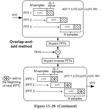
Hi Rick,
Sorry I should have been clear when I made that link/reference; you are correct about what was on that page but I should have said "start with this page and read through until you get to the section about filtering (which includes a matlab example)".
Specifically the discussion about the COLA constraints on windows seemed relevant to some of the prior comments/questions.
But now that we've hijacked this thread for a sidebar discussion, I'm wondering if when I was experimenting with FFT->IFFT I maybe overlooked/misunderstood something about windowing & overlap-add. I don't have your book but if you've got a section on that it would be a good reason for me to get it ;^)
My system included time domain interpolation (done on the FFT and in the end the filter part went away, so now just interpolation via FFT/IFFT overlap-add), so it's not the same as ctlee's (more conventional) case.
A certainly got the "wrong answers" with a rectangular window on the input data and raised cosine got the THD+N of interpolator down to below -120 dB target.
Thanks,
Brewster
Hi Brewster. Please send me a private e-mail at:
R_dot_Lyons_@_ieee_dot_org.
[-Rick-]
Hi Rick,
Thanks for the comment. I never thought and tried to window the filter in the time domain coefficient (which is \( h[n] \) in this thread). I'll have a look at your book, it's in my hands :)
And you were correct, the figure that's what I actually tried to implement. But I think I ended up with a different direction using 'synthesis window' thing.
But set this aside, I still have a doubt about the length of the synthesis window since it is not the same length with the window applied before filtering. But applying synthesis windows is not the issue in this "fast convolution" topic, so maybe I'll look for other references (for example, [49] in https://www.dsprelated.com/freebooks/sasp/Weighted...).
--- update ---
I've already mentioned in the reply to @ZaellixA, I found something hard to understand. From the link above, we can find how to do WOLA process. I thought "process" in the 3rd step is the filtering, but it seems not. Otherwise the input and output signals cannot have the same length \( N \).
This "process" might be different from filtering, I think I have to have a look at this to figure out what people do in this step.
--- end of update ---
Thanks for your comment!
Sincerely,
ctlee
The link does say:
Output windows are not used in simple FFT convolution processors


