


Filtered-Feedback Comb Filters
The filtered-feedback comb filter (FFBCF) uses filtered feedback instead of just a feedback gain.
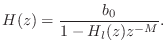
Denoting the feedback-filter transfer function by ![]() , the
transfer function of the filtered-feedback comb filter can be written
as
, the
transfer function of the filtered-feedback comb filter can be written
as
In §2.6.2 above, we mentioned the physical interpretation of a feedback-comb-filter as simulating a plane-wave bouncing back and forth between two walls. Inserting a lowpass filter in the feedback loop further simulates frequency dependent losses incurred during a propagation round-trip, as naturally occurs in real rooms.
The main physical sources of plane-wave attenuation are air absorption (§B.7.15) and the coefficient of absorption at each wall [349]. Additional ``losses'' for plane waves in real rooms occur due to scattering. (The plane wave hits something other than a wall and reflects off in many different directions.) A particular scatterer used in concert halls is textured wall surfaces. In ray-tracing simulations, reflections from such walls are typically modeled as having a specular and diffuse component. Generally speaking, wavelengths that are large compared with the ``grain size'' of the wall texture reflect specularly (with some attenuation due to any wall motion), while wavelengths on the order of or smaller than the texture grain size are scattered in various directions, contributing to the diffuse component of reflection.
The filtered-feedback comb filter has many applications in computer music. It was evidently first suggested for artificial reverberation by Schroeder [412, p. 223], and first implemented by Moorer [314]. (Reverberation applications are discussed further in §3.6.) In the physical interpretation [428,207] of the Karplus-Strong algorithm [236,233], the FFBCF can be regarded as a transfer-function physical-model of a vibrating string. In digital waveguide modeling of string and wind instruments, FFBCFs are typically derived routinely as a computationally optimized equivalent forms based on some initial waveguide model developed in terms of bidirectional delay-lines (``digital waveguides'') (see §6.10.1 for an example).
For stability, the amplitude-response of the feedback-filter
![]() must be less than
must be less than ![]() in magnitude at all frequencies, i.e.,
in magnitude at all frequencies, i.e.,
![]() .
.
Next Section:
Equivalence of Parallel Combs to TDLs
Previous Section:
Feedback Comb Filter Amplitude Response


