


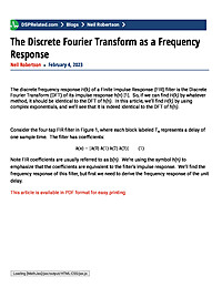
The Discrete Fourier Transform as a Frequency Response
The discrete frequency response H(k) of a Finite Impulse Response (FIR) filter is the Discrete Fourier Transform (DFT) of its impulse response h(n) [1]. So, if we can find H(k) by whatever method, it should be identical to the DFT of...
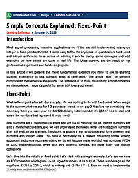
Simple Concepts Explained: Fixed-Point
IntroductionMost signal processing intensive applications on FPGA are still implemented relying on integer or fixed-point arithmetic. It is not easy to find the key ideas on quantization, fixed-point and integer arithmetic. In a series of...
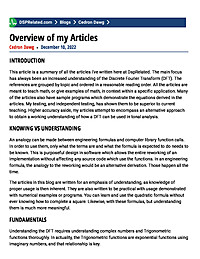
Overview of my Articles
Introduction This article is a summary of all the articles I've written here at DspRelated. The main focus has always been an increased understanding of the Discrete Fourier Transform (DFT). The references are grouped by topic and ordered in...
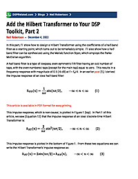
Add the Hilbert Transformer to Your DSP Toolkit, Part 2
In this part, I’ll show how to design a Hilbert Transformer using the coefficients of a half-band filter as a starting point, which turns out to be remarkably simple. I’ll also show how a half-band filter can be synthesized using the...
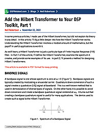
Add the Hilbert Transformer to Your DSP Toolkit, Part 1
In some previous articles, I made use of the Hilbert transformer, but did not explain its theory in any detail. In this article, I’ll dig a little deeper into how the Hilbert Transformer works. Understanding the Hilbert Transformer...
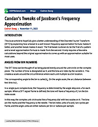
Candan's Tweaks of Jacobsen's Frequency Approximation
Introduction This is an article to hopefully give a better understanding of the Discrete Fourier Transform (DFT) by explaining how a tweak to a well known frequency approximation formula makes it better, and another tweak makes it exact. The...
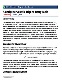
A Recipe for a Basic Trigonometry Table
Introduction This is an article that is give a better understanding to the Discrete Fourier Transform (DFT) by showing how to build a Sine and Cosine table from scratch. Along the way a recursive method is developed as a tone generator for a...
A New Contender in the Quadrature Oscillator Race
There have been times when I wanted to determine the z-domain transfer function of some discrete network, but my algebra skills failed me. Some time ago I learned Mason's Rule, which helped me solve my problems. If you're willing to learn the...
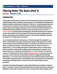
Filtering Noise: The Basics (Part 1)
IntroductionFinding signals in the presence of noise is one of the fundamental quests of the discipline of signal processing. Noise is inherently random by nature, so a probability oriented approach is needed to develop a mathematical framework...
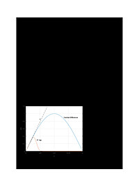
Evaluate Noise Performance of Discrete-Time Differentiators
When it comes to noise, all differentiators are not created equal. Figure 1 shows the magnitude response of two differentiators. They both have a useful bandwidth of a little less than π/8 radians (based on maximum magnitude response...
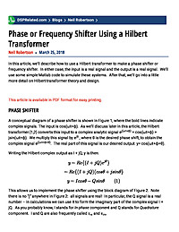
Phase or Frequency Shifter Using a Hilbert Transformer
In this article, we'll describe how to use a Hilbert transformer to make a phase shifter or frequency shifter. In either case, the input is a real signal and the output is a real signal. We'll use some simple Matlab code to simulate these systems. After that, we'll go into a little more detail on Hilbert transformer theory and design.
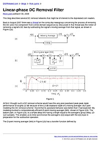
Linear-phase DC Removal Filter
This blog describes several DC removal networks that might be of interest to the dsprelated.com readers. Back in August 2007 there was a thread on the comp.dsp newsgroup concerning the process of removing the DC (zero Hz) component from a...
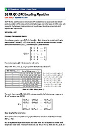
5G NR QC-LDPC Encoding Algorithm
3GPP 5G has been focused on structured LDPC codes known as quasi-cyclic low-density parity-check (QC-LDPC) codes, which exhibit advantages over other types of LDPC codes with respect to the hardware implementations of encoding and decoding using...
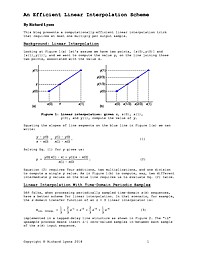
An Efficient Linear Interpolation Scheme
This article presents a computationally-efficient linear interpolation trick that requires at most one multiply per output sample.
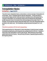
Interpolation Basics
This article covers interpolation basics, and provides a numerical example of interpolation of a time signal. Figure 1 illustrates what we mean by interpolation. The top plot shows a continuous time signal, and the middle plot shows a sampled version with sample time Ts. The goal of interpolation is to increase the sample rate such that the new (interpolated) sample values are close to the values of the continuous signal at the sample times [1]. For example, if we increase the sample rate by the integer factor of four, the interpolated signal is as shown in the bottom plot. The time between samples has been decreased from Ts to Ts/4.
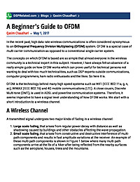
A Beginner's Guide to OFDM
In the recent past, high data rate wireless communications is often considered synonymous to an Orthogonal Frequency Division Multiplexing (OFDM) system. OFDM is a special case of multi-carrier communication as opposed to a conventional...
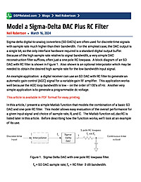
Model a Sigma-Delta DAC Plus RC Filter
Sigma-delta digital-to-analog converters (SD DAC’s) are often used for discrete-time signals with sample rate much higher than their bandwidth. For the simplest case, the DAC output is a single bit, so the only interface hardware required is a standard digital output buffer. Because of the high sample rate relative to signal bandwidth, a very simple DAC reconstruction filter suffices, often just a one-pole RC lowpass. In this article, I present a simple Matlab function that models the combination of a basic SD DAC and one-pole RC filter. This model allows easy evaluation of the overall performance for a given input signal and choice of sample rate, R, and C.
Simple Concepts Explained: Fixed-Point
IntroductionMost signal processing intensive applications on FPGA are still implemented relying on integer or fixed-point arithmetic. It is not easy to find the key ideas on quantization, fixed-point and integer arithmetic. In a series of...
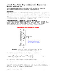
A Fast Real-Time Trapezoidal Rule Integrator
This article presents a computationally-efficient network for computing real?time discrete integration using the Trapezoidal Rule.


